Lyptus Cabinets- Lower Peninsula Cabinets Continued- Back and End Panels
This web page is generally organized with the oldest on top and the newest at the bottom.
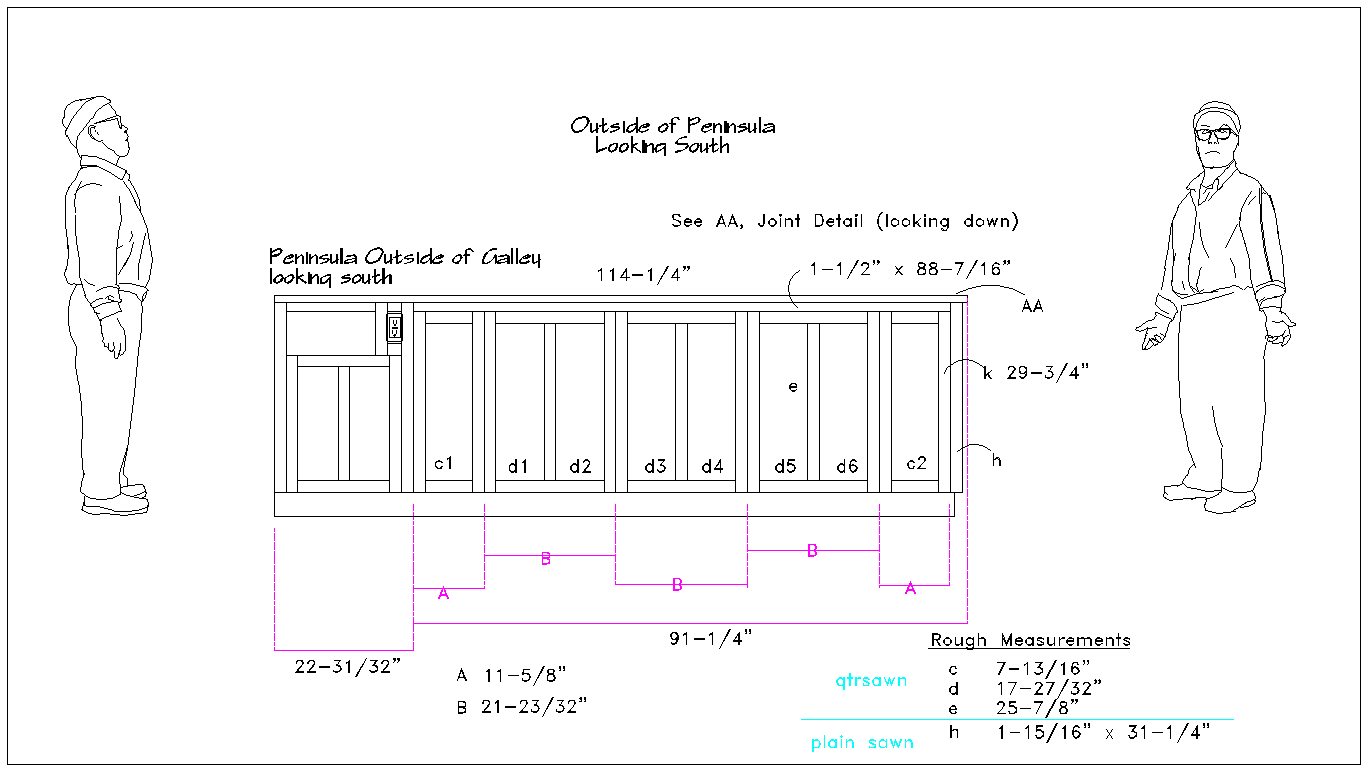
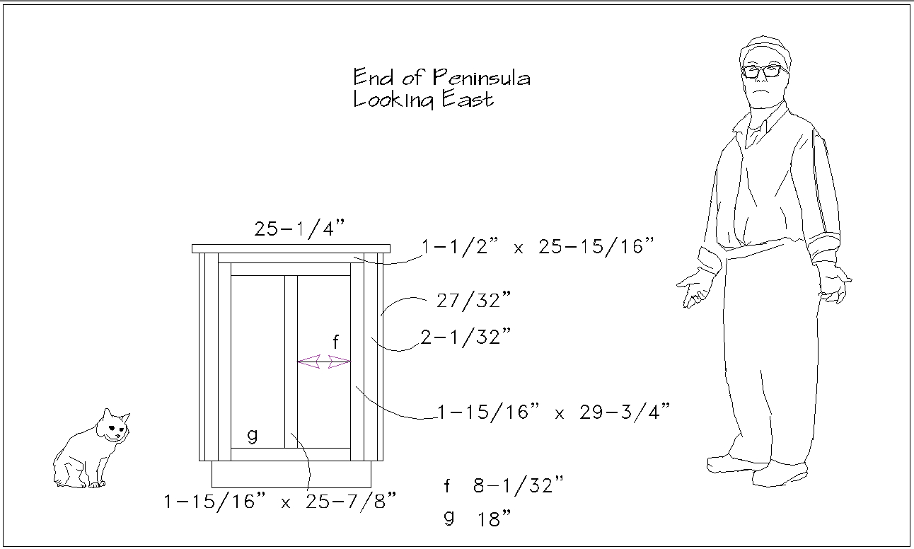
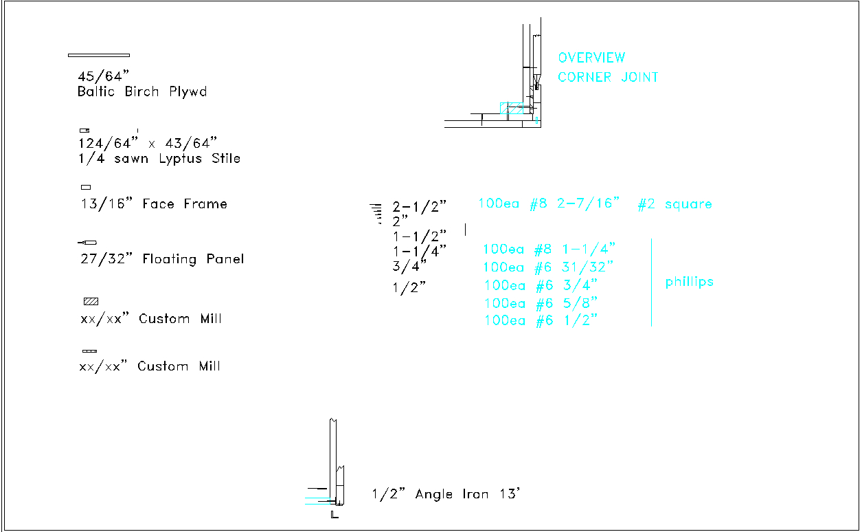
I considered just putting up lyptus plywood. If I had, this would have been done long ago. But no, I'll stick with the plan of quartersawn stiles and rails with plainsawn floating panels. The real challenge here is no exposed connections like brad nails or screws. This can be accomplished with a structural mounting frame, 1/2" angle iron and screws. The only problem is the 88" frieze. There is no way to connect it from the back so I will use inset holes drilled with a forstner bit, screws, and wood plugs for it. I'm considering contrasting plugs of bloodwood for some punch but its mostly out of sight under the countertop overhang so probably not. The 1/2" iron angle iron to support all the panels is the thing that makes all this possible. I really stressed about what to do to make this all work until I remembered woodworker's rule #5- When you don't know how to solve a woodworking problem use some steel. I won't have to glue the mortise and tenons together as all the panels fit together with compression due to the zero clearance fitting of the panels between the false pillars, angle iron, and the top frieze. I also treated the iron with phosphoric acid. I figure inaccessible iron needs treatment because I don't want iron rust drips to ever stain the wood or floor.
:
The space was divided up so the resulting panel sizes could be accommodated by whole boards I have in stock. This was done to minimize the glue-up work required and more importantly show off the spectacular nature of a lyptus tree.
Click on a drawing to download a PDF.
:
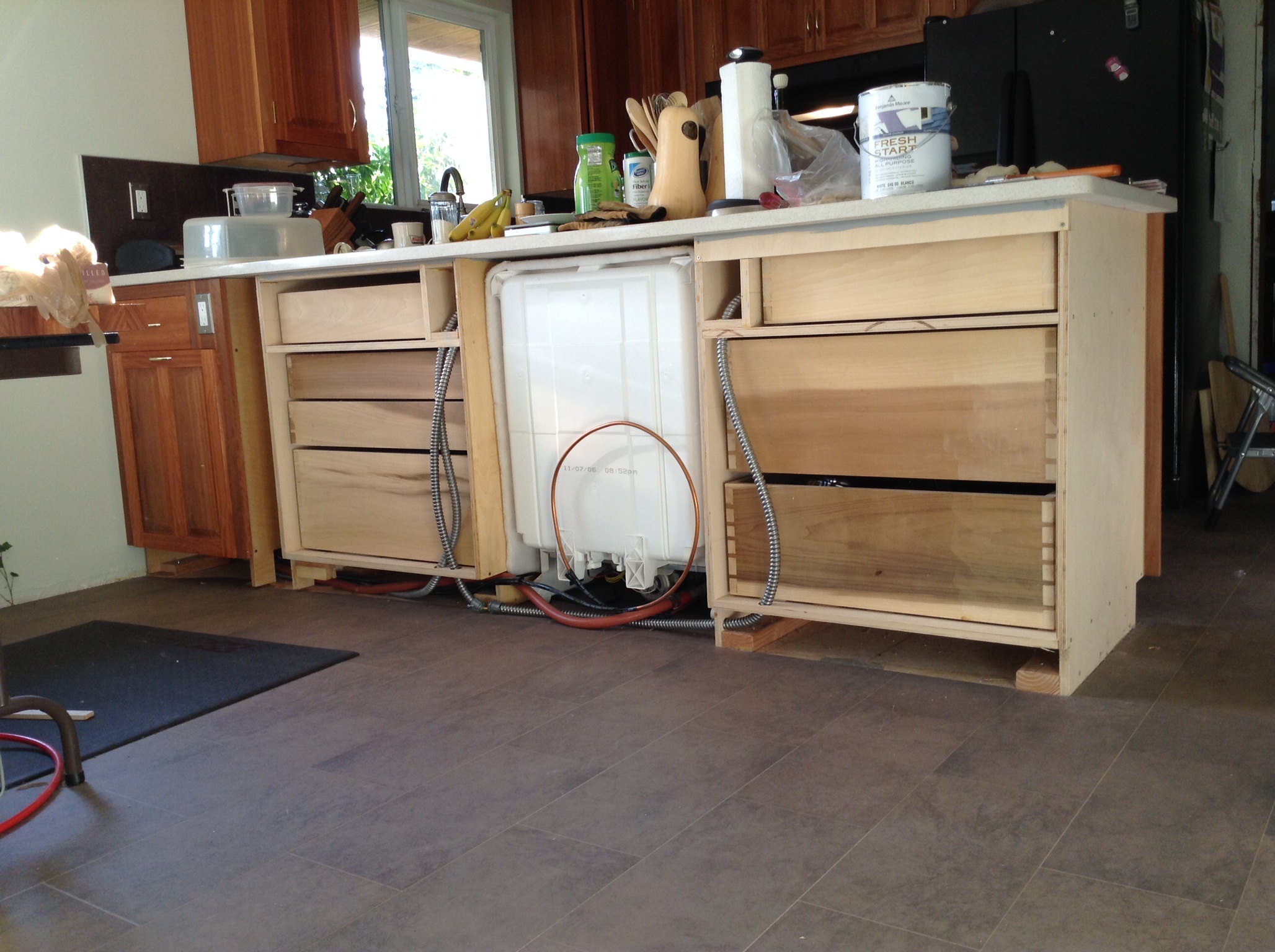
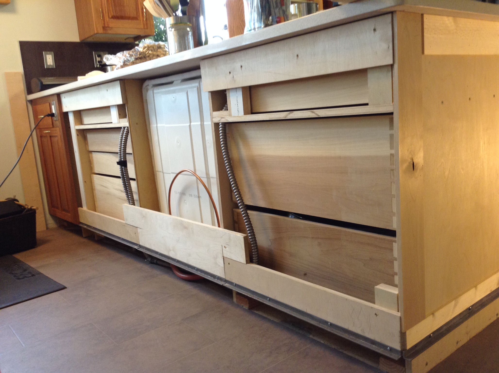
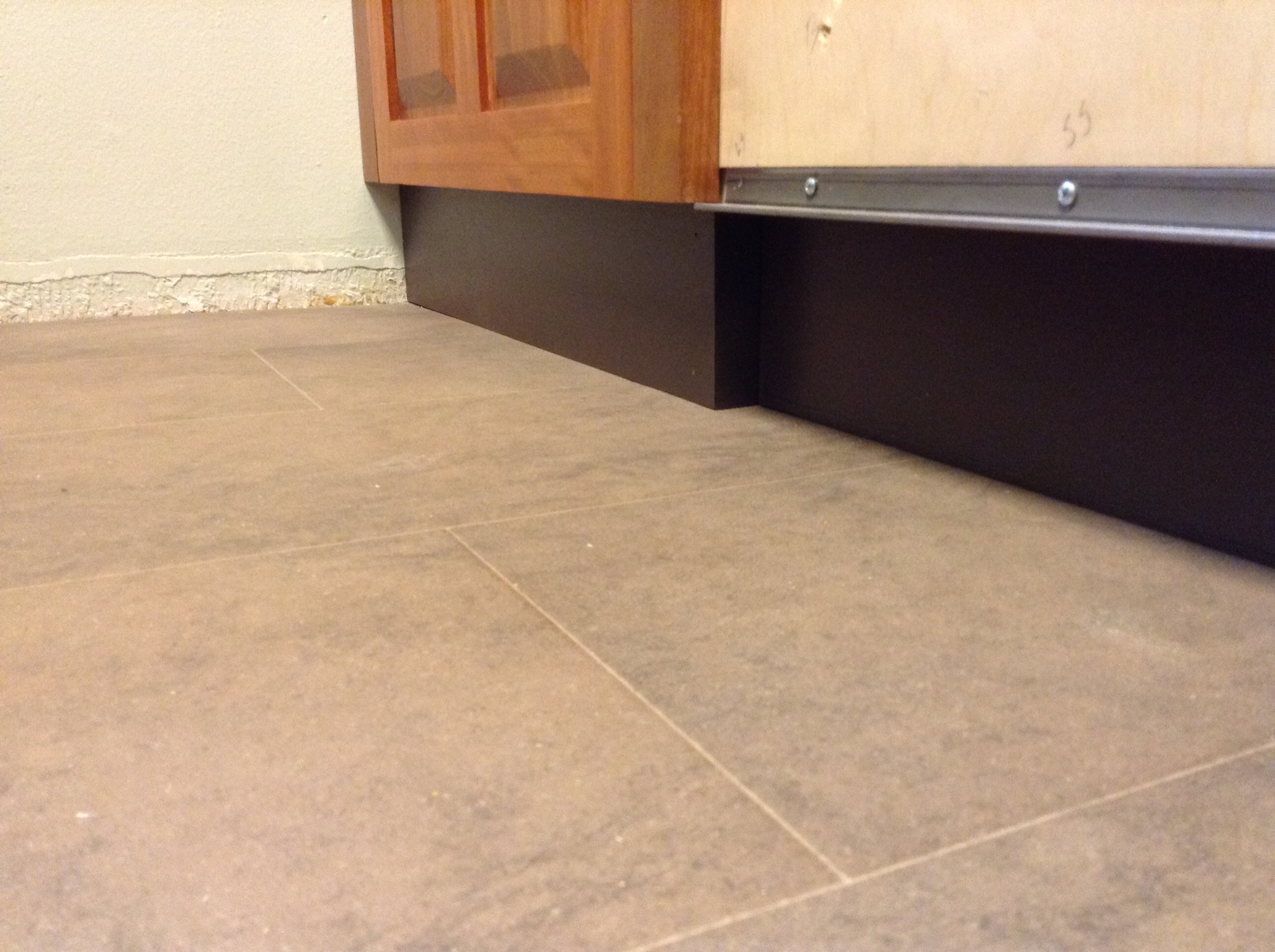
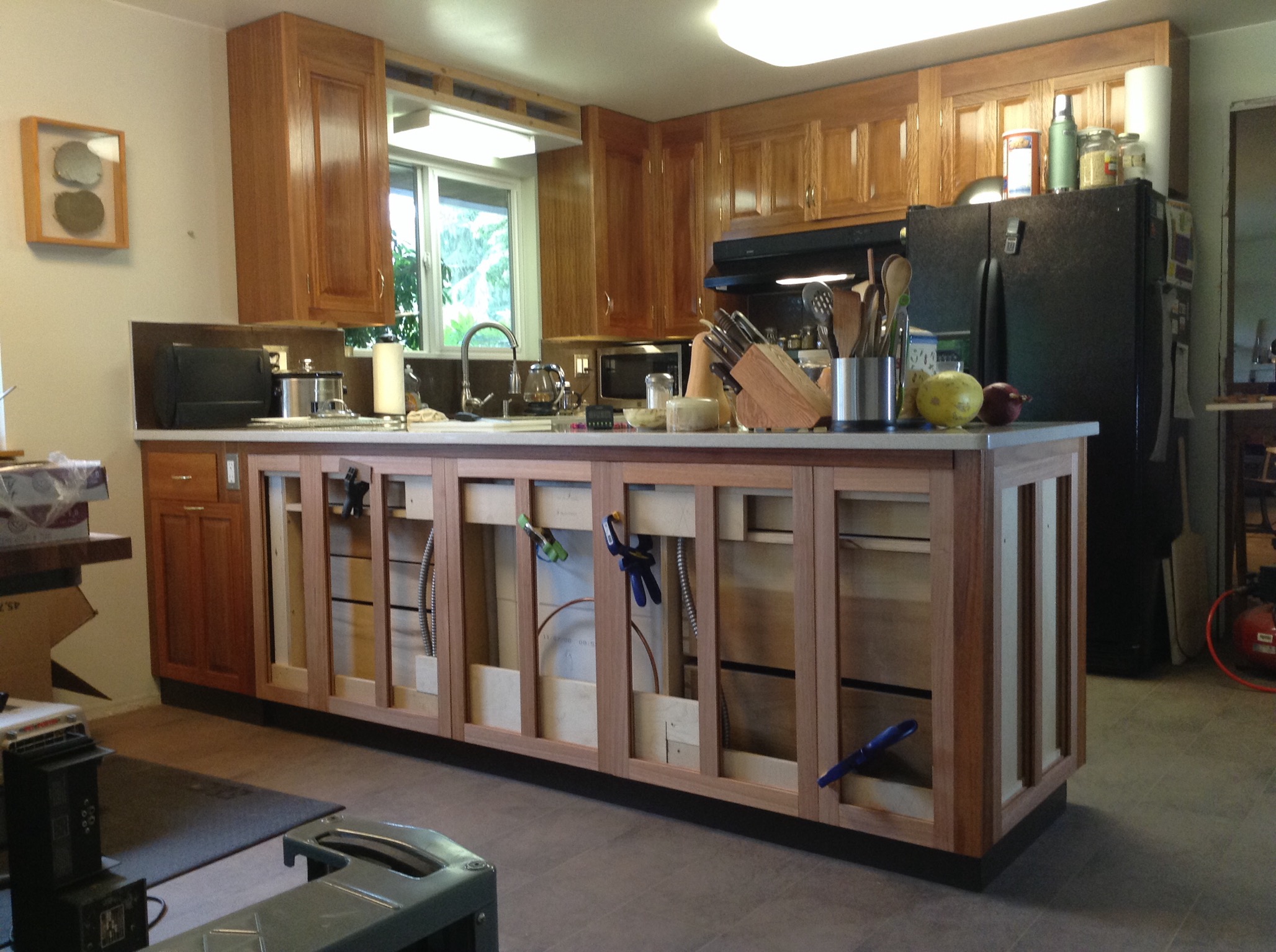
The Situation- Cabinet Carcasses With No Backside or End Panels
:
Details of Joints and Angle Iron
3D analysis of joints keeps the monster away.
:
Sub Structure
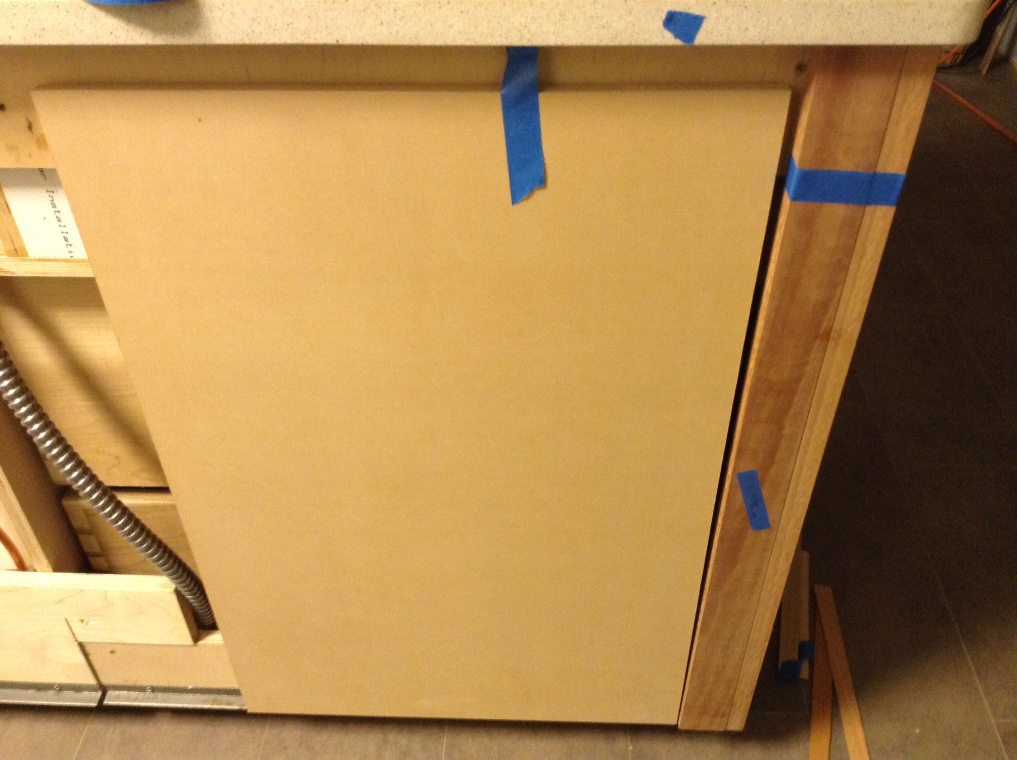
Here the 1/2" angle iron, structural mounting frame and fillers have been installed. Missing is the top bridge behind the dishwasher in the middle. There will be a two lite panel there and I can't easily get back there to drill a screw from inside. I don't want to have to pull the dishwasher. In this case I'll screw the panel to the lower and upper bridge first, place this panel in the cabinet and screw the bridges from the inside on either side of the dishwasher.
:
False Pillars
False pillars for the cabinet ends. These will be finished and installed first so everything can be built to fit between them. You can see the continuous floating long tenon at the end of the joint. I can't install a tenon on the inside pillar because I didn't think that far ahead. I got better surface alignment on the untenoned joint. Go figure... OK I'm back, I didn't get a good fit on the tenoned joint because I didn't inspect and test well before the glue was applied or it slipped in the glue up panic or both. When faces miss by even 1/64th you can see it. The ray fleck on the figured side is wonderful.
:
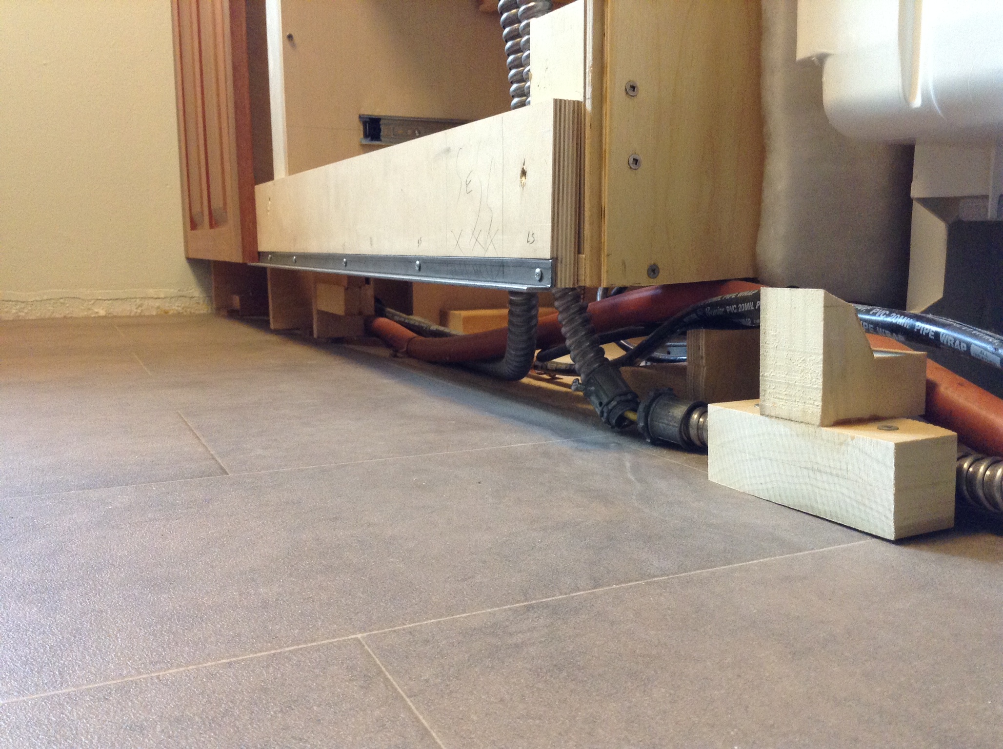
Toe Kick Structure
First task; complete the toe kick and install the panel attachment grid. You can see the mounting blocks and section of mounting structure with inset angle iron. Due to the cutout required for utilities I installed a toe kick brace of poplar. You can see part of the angle iron support to the left of the brace.
:
Ready for the toe kick installation.
:
Toe Kick Materials and Surface Preparations
Primed and painted 1/4" plywood toe kick material. When choosing a color I googled toe kick and 99.99% of the images were white or light colored. White toe kicks show off shoe marks. Why would I want that cleaning job? Don't believe the internet. Due to the slope of the home these toe kicks have some long tapers to fit tight. I cut these long tapers with the ripping sled.
:
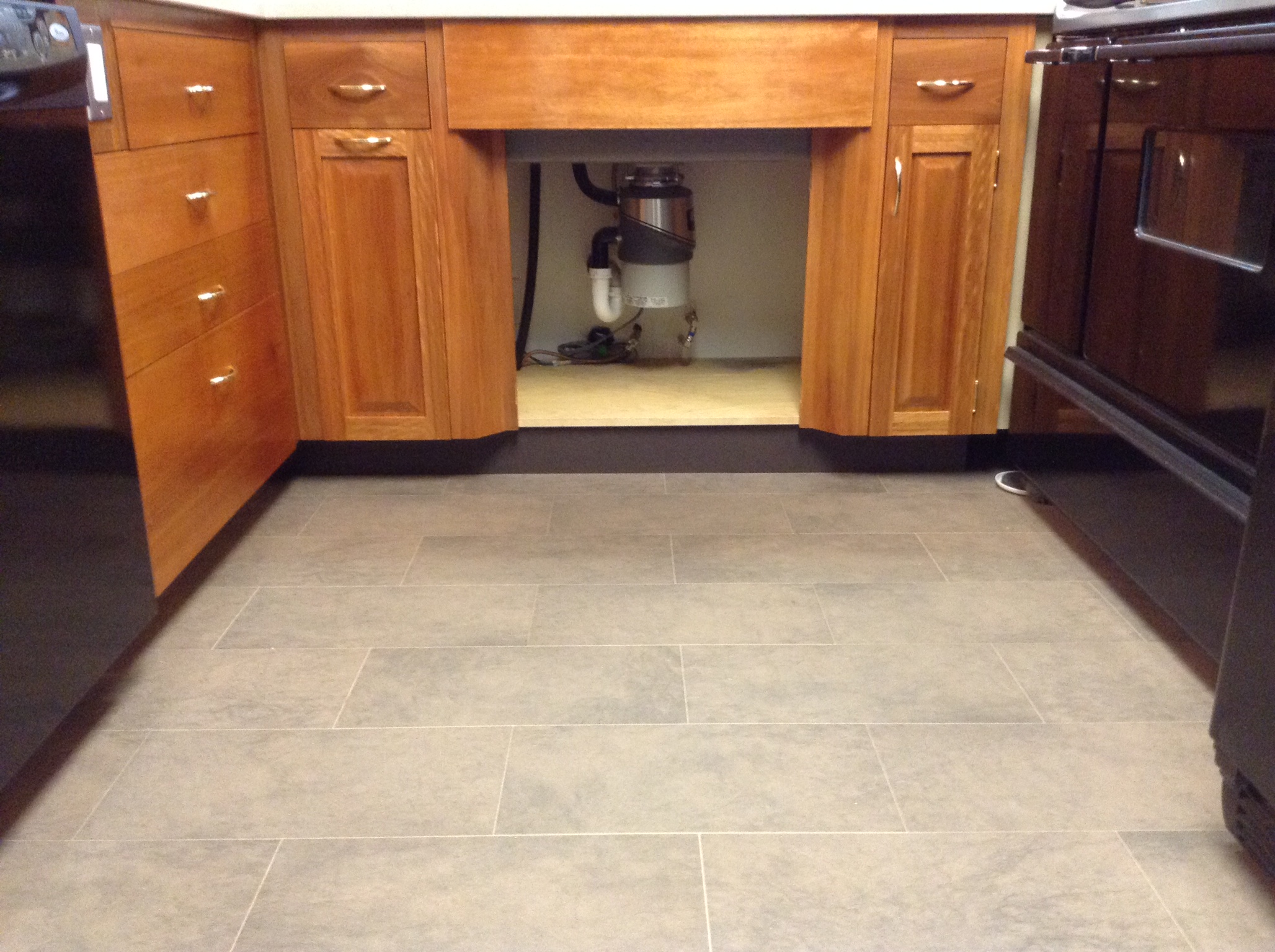
Toe Kick Installation
Toe kick installed under the sink in the galley.
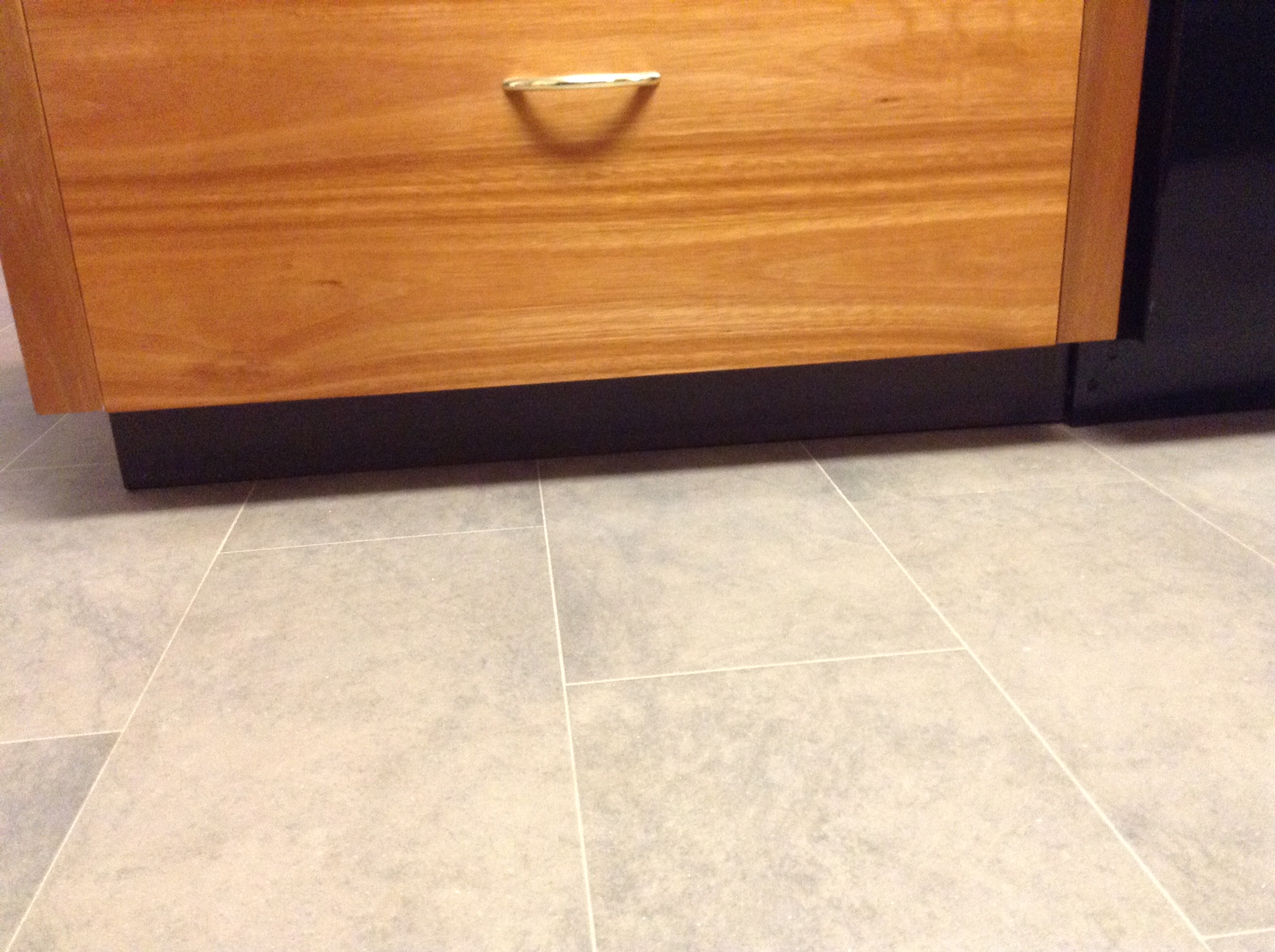
:
Toe kick at the end of the cabinet in the galley.
:
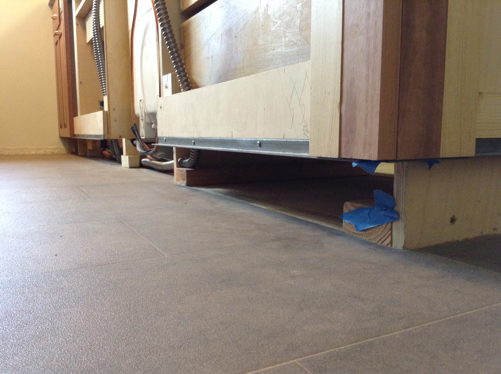
Toe kick at the cabinet end.
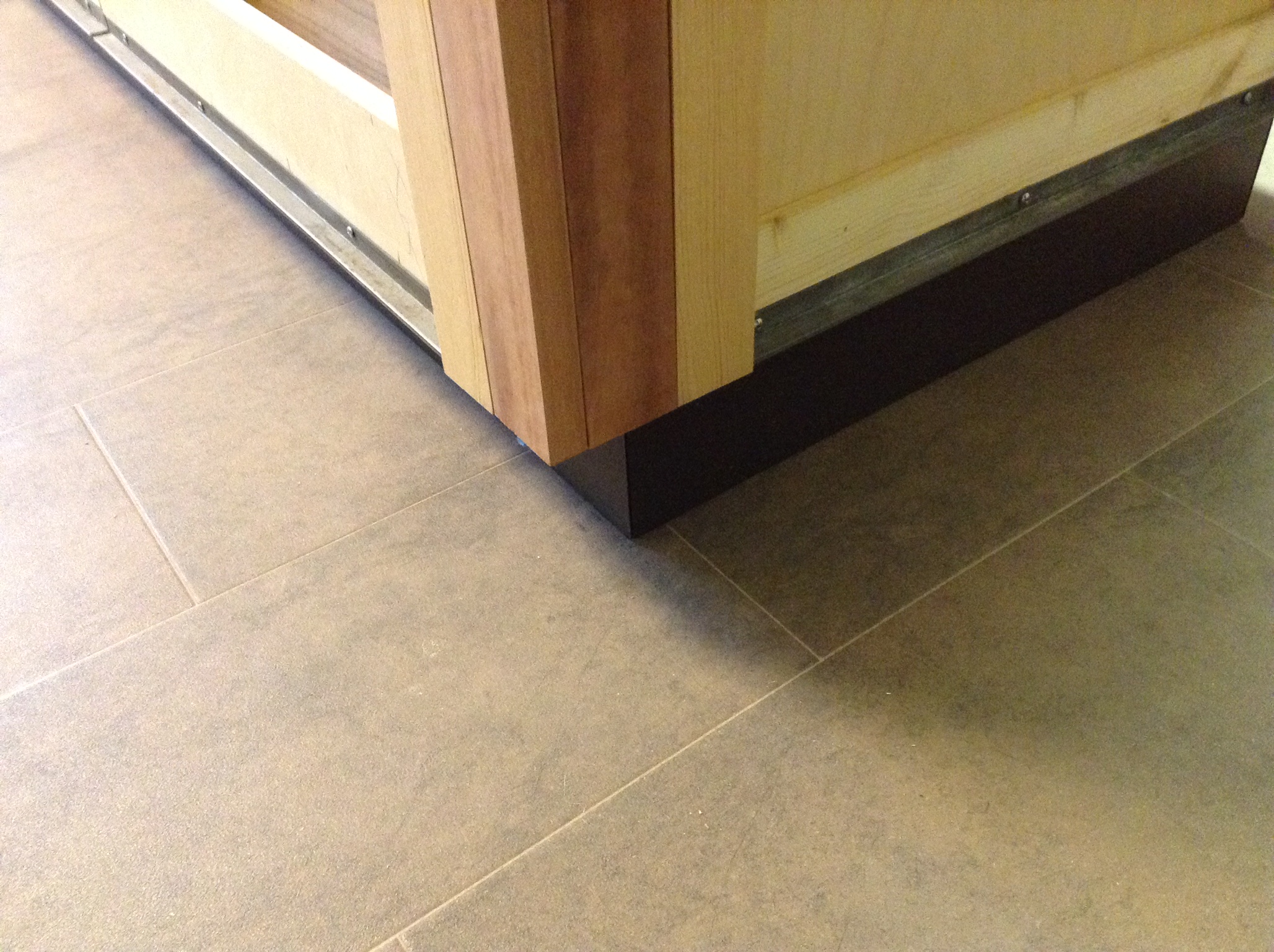
:
Toe kick at the return wall. The proud toe kick under the end cabinet was the result of a cabinet construction error. As this cabinet is a pull out and so close to the wall a toe kick isn't really needed.
:
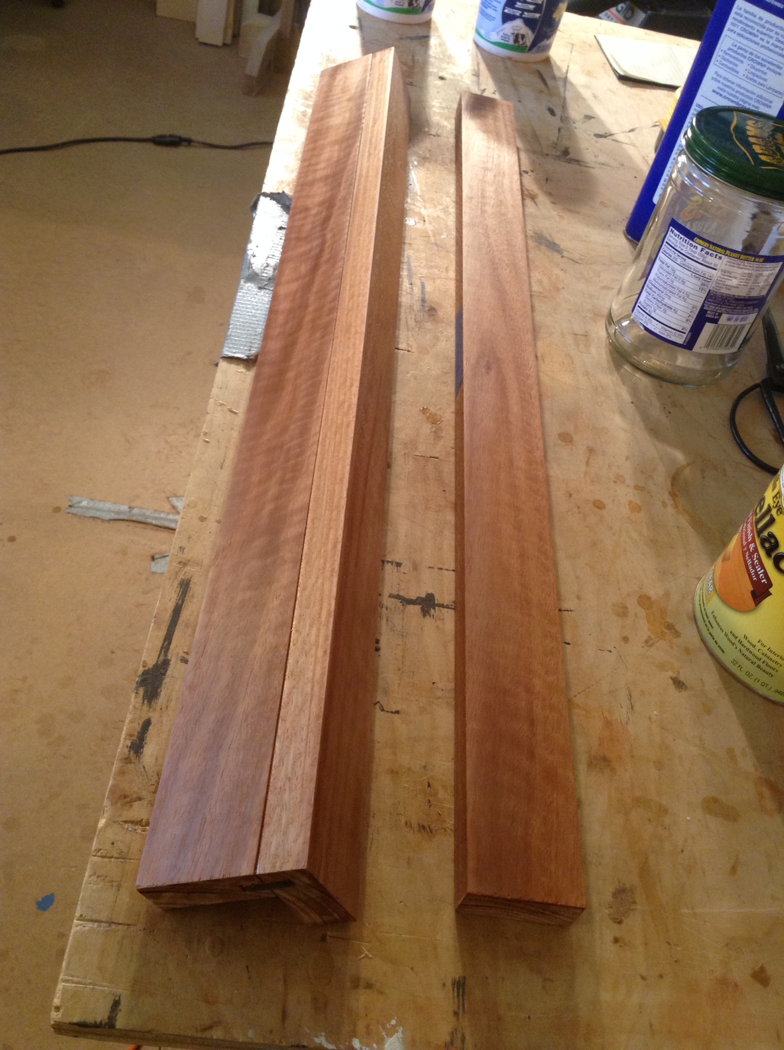
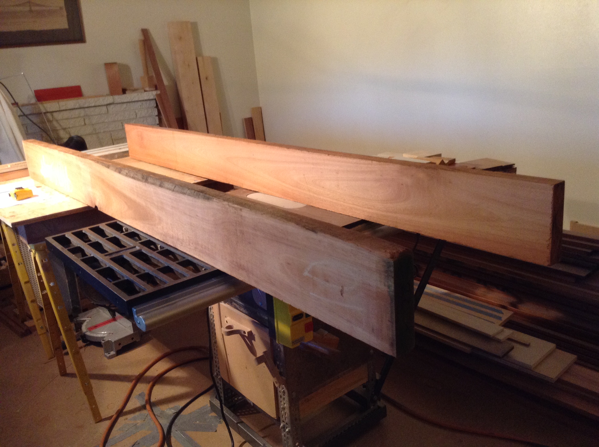
Stiles and Rails of Quartersawn Lyptus
Two 8' lyptus timbers to be quartersawn.
:
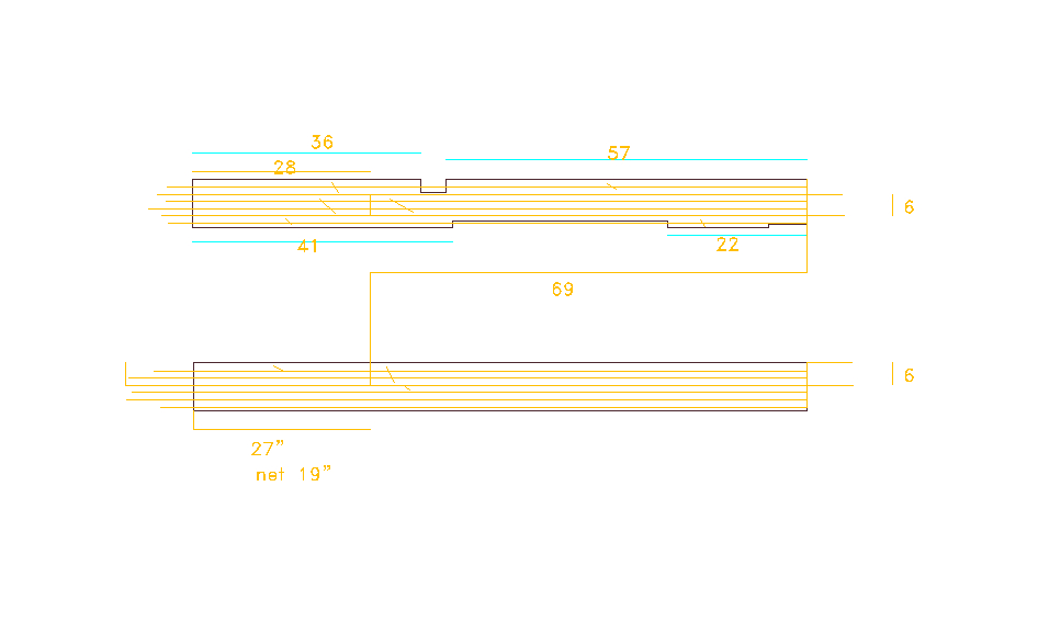
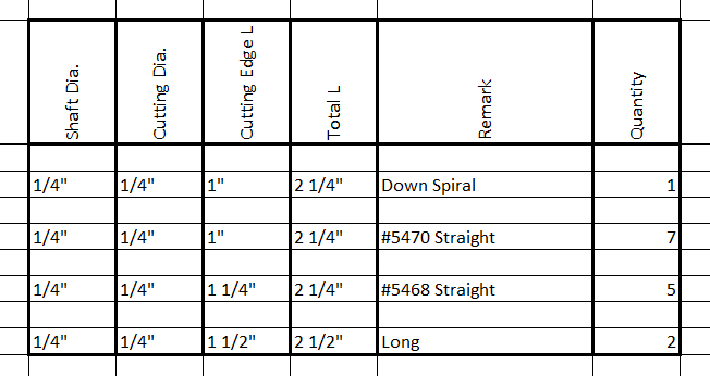
Cut Diagram
Cut diagram used to determine net quartersawn boards. There will be almost nothing left over when all is completed.
:
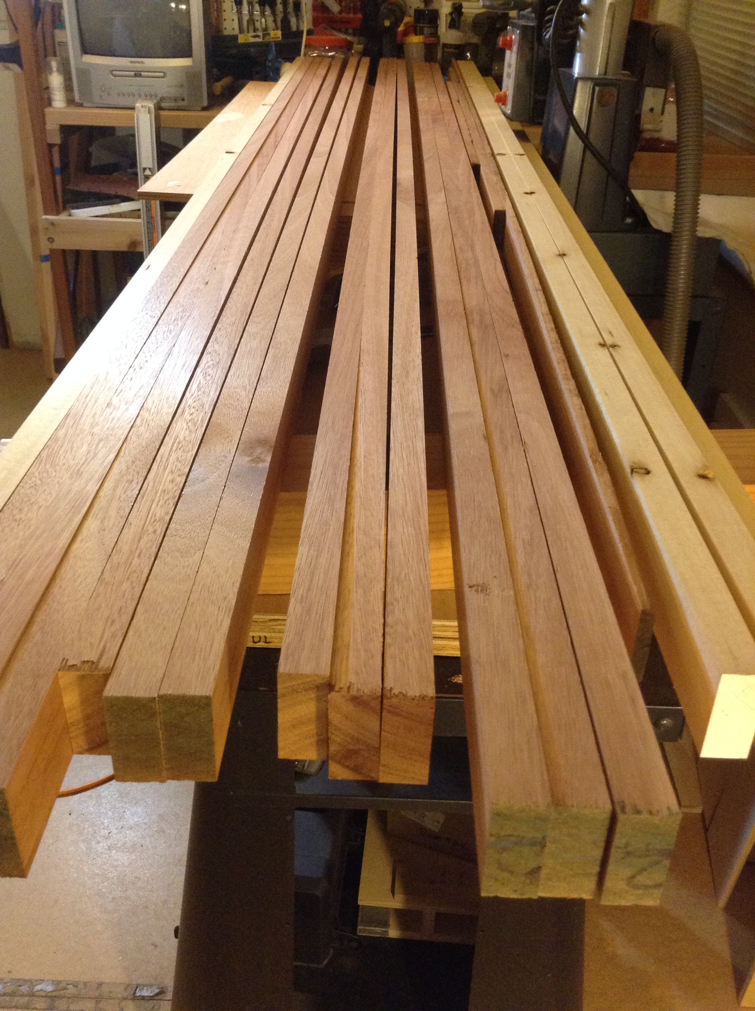
Lyptus After Ripping and Planing
I always mill some secondary wood to use as test material. Material that bows usually becomes the shorter pieces to minimize the height of the arc.
:
After sanding. I hate snipe so I try to work with long stock to minimize waste.
:
Quality control #1.
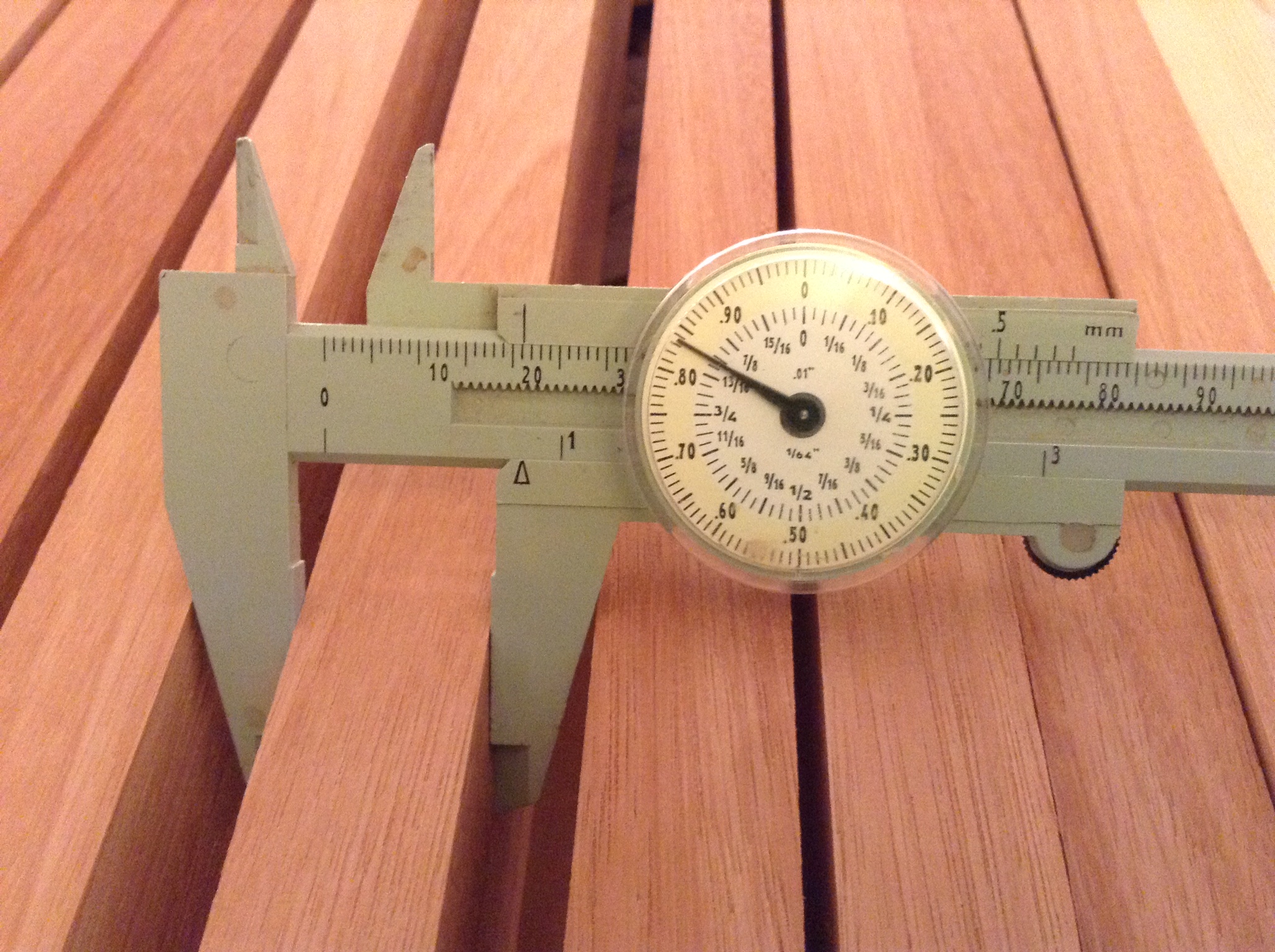
:
Quality control #2. This is the quartersawn face. Isn't this stuff beautiful.
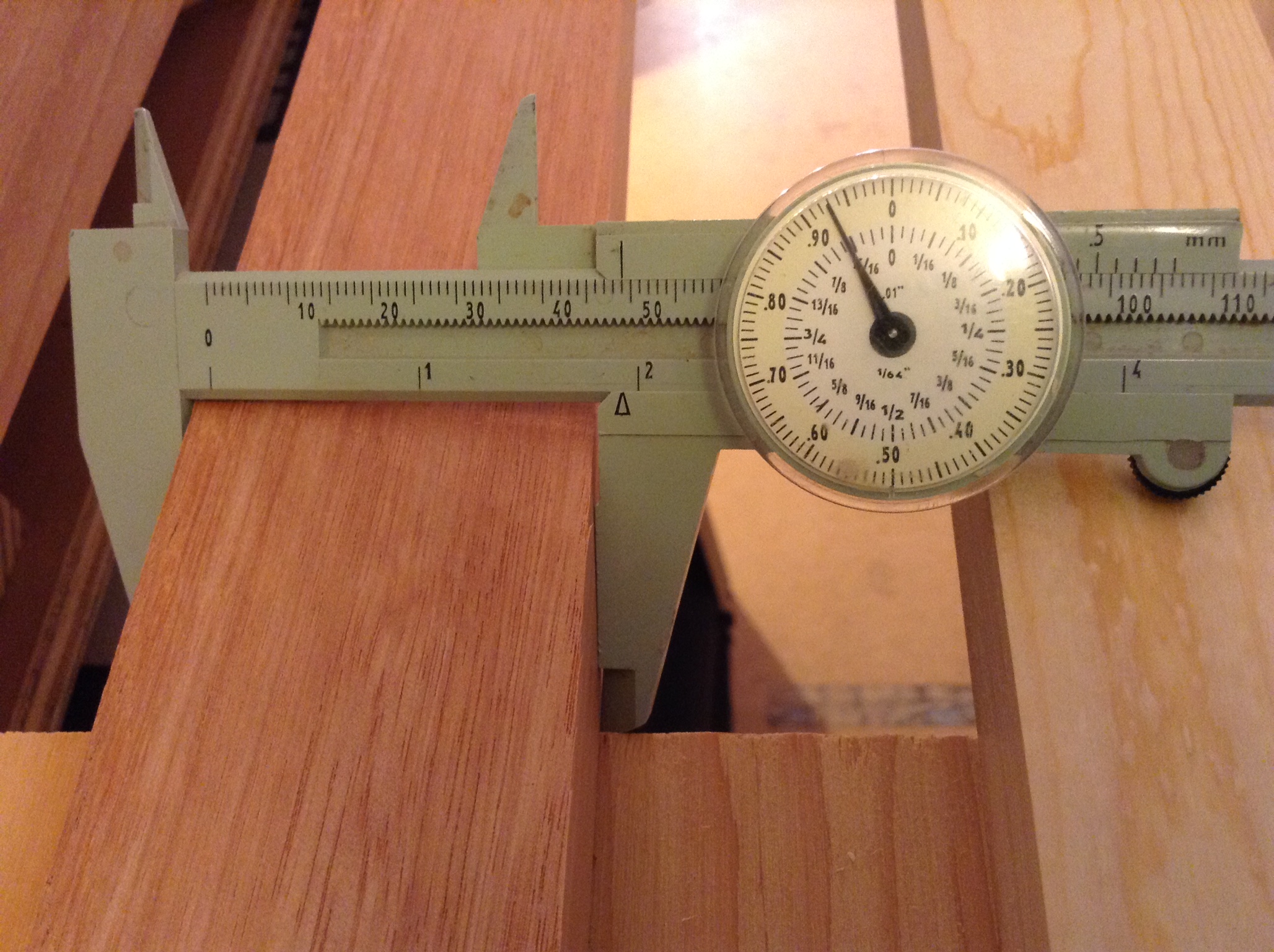
:
Milling process.
:
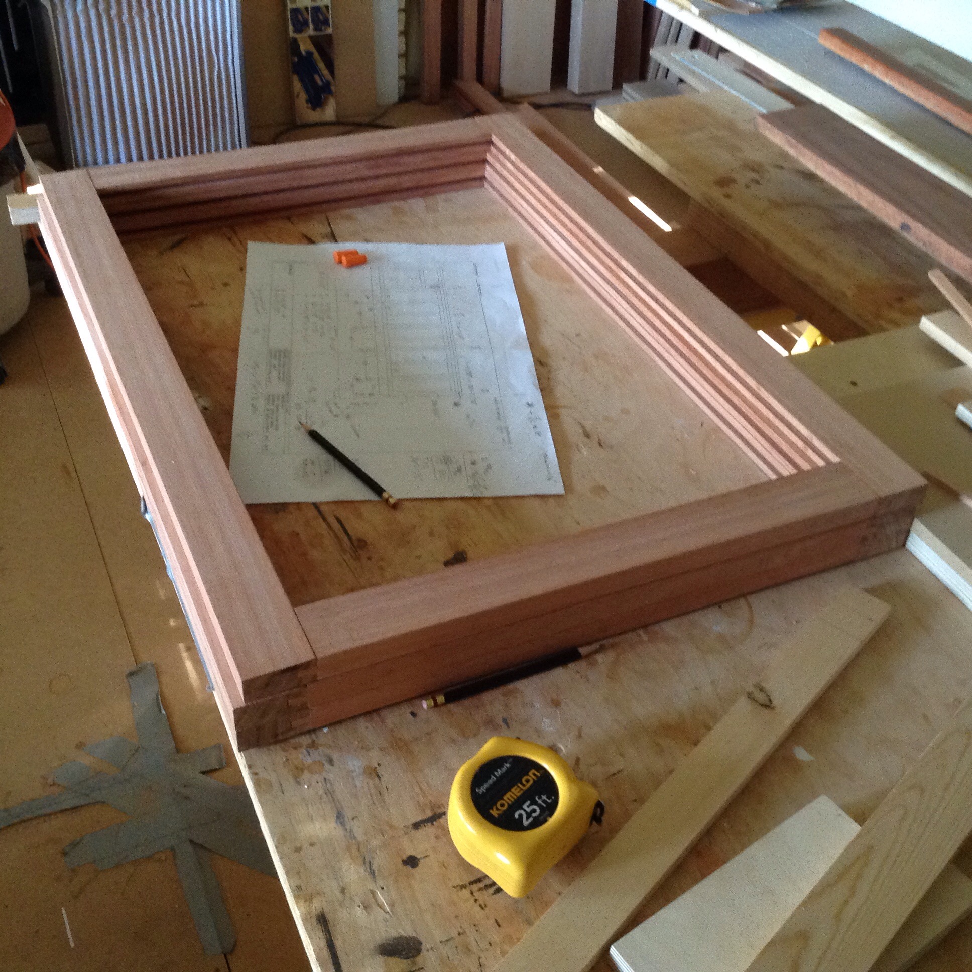
Assembling frames.
:
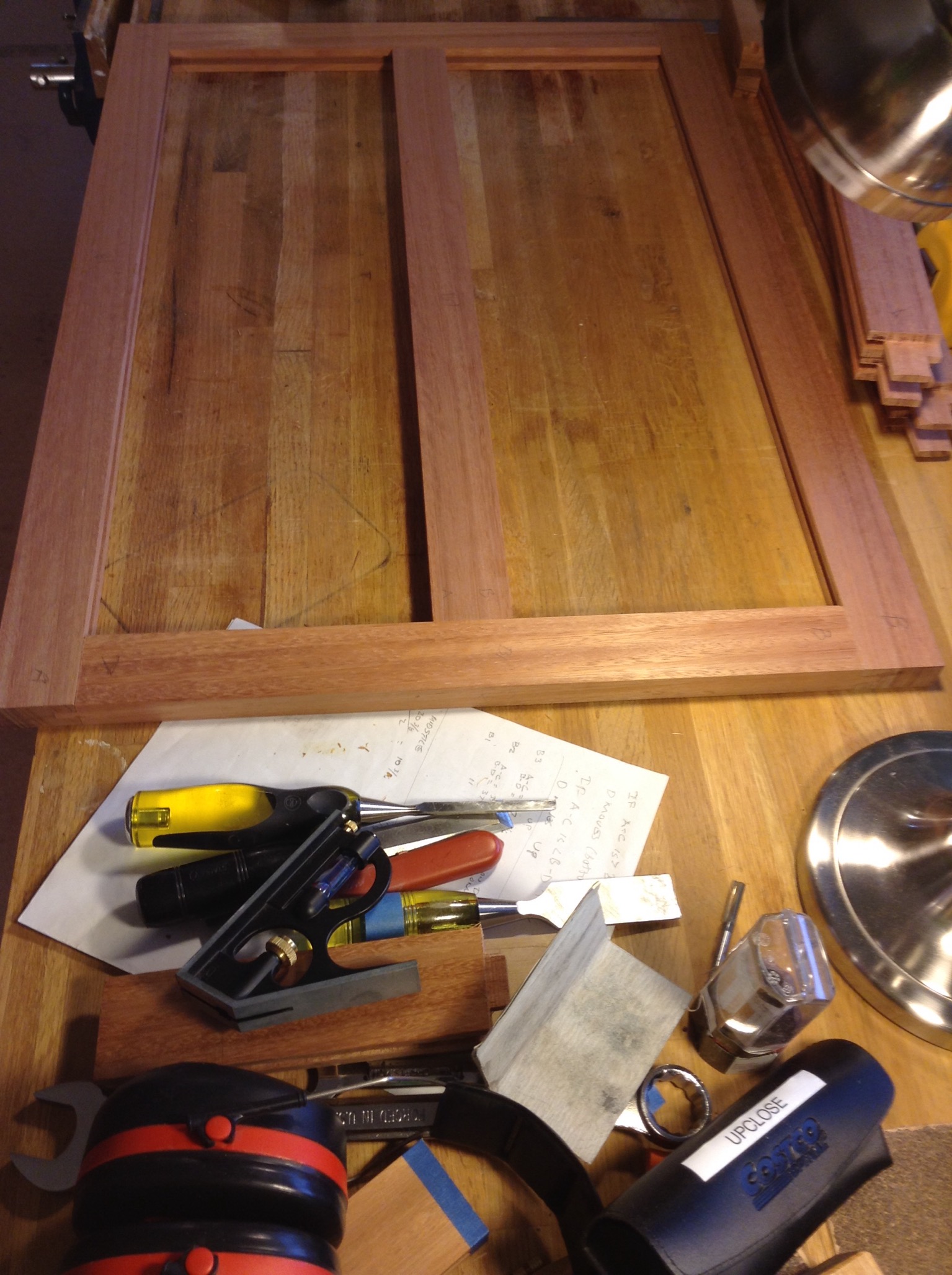
Frames as two lite.
:
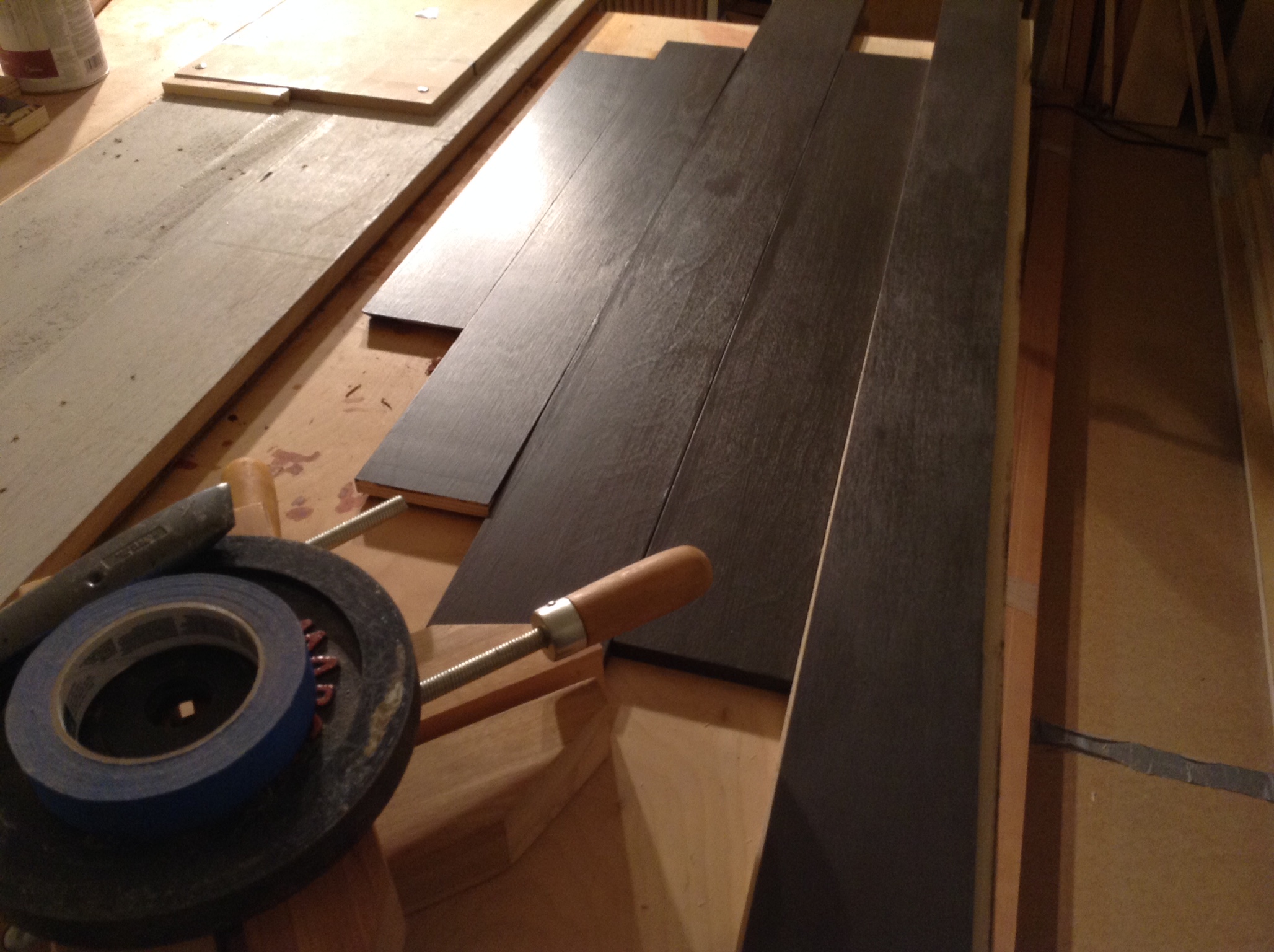
Zero Tolerance Fitting and Tequila
It must have been summer. Fitting the frames to the cabinet so there are no gaps and the joints are under slight compression.
:
This was the worst; 1/4" out of square. This should not happen but it did. Hiding errors is part of good craftsmanship. I use a near perfect rectangle blank to determine the adjustment needed. I then cut the corresponding stile to fit perfectly with a ripping sled on the table saw. This way the inside of the frame is square and the outside isn't.
:
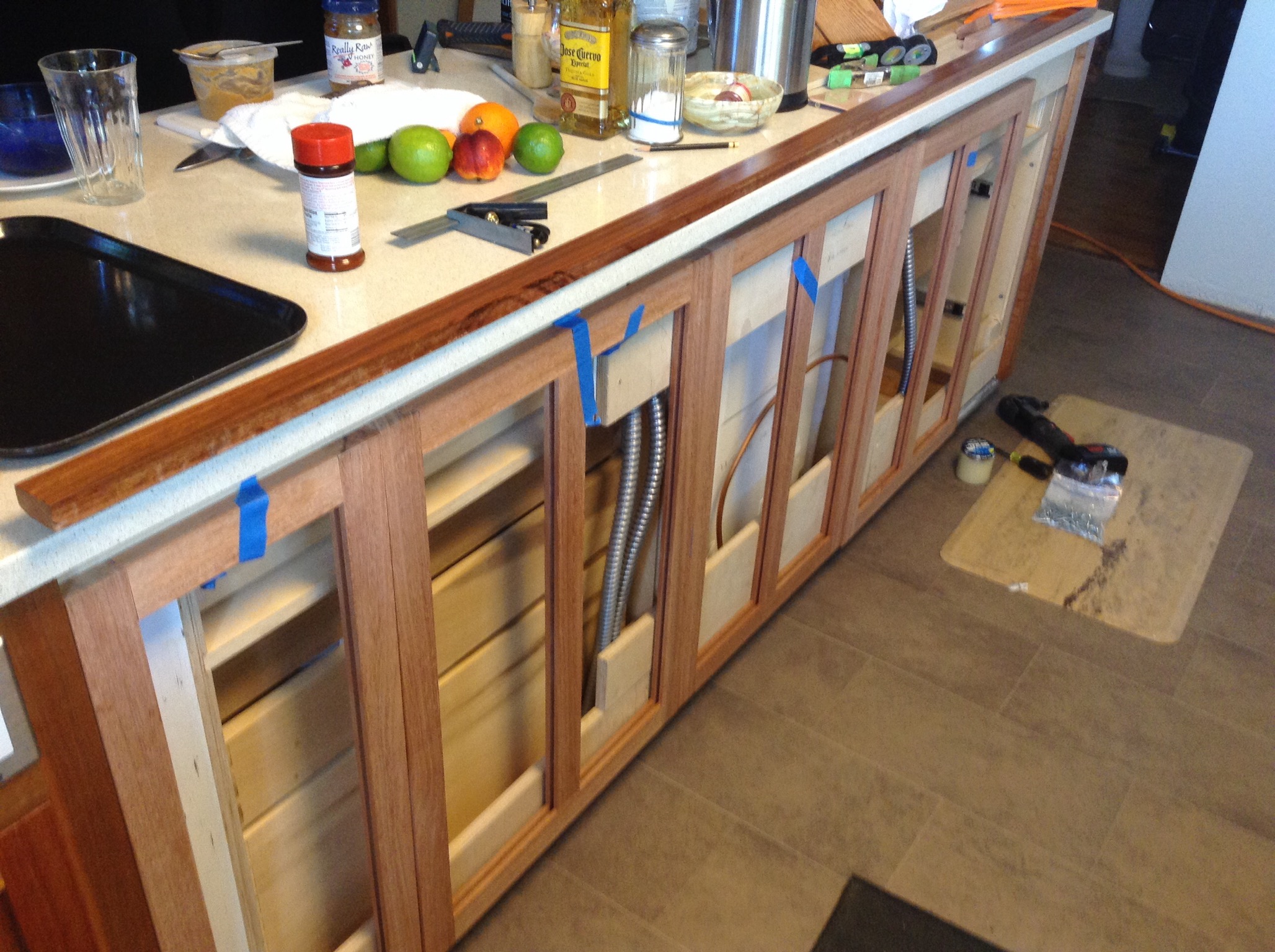
Fitted
The peninsula cabinet with all the quartersawn lyptus frames fit to the cabinet. I can't forget to install some sound muffling material behind the washer before it's all walled up. I'm considering Buffalo Batting from Joann's.
:::
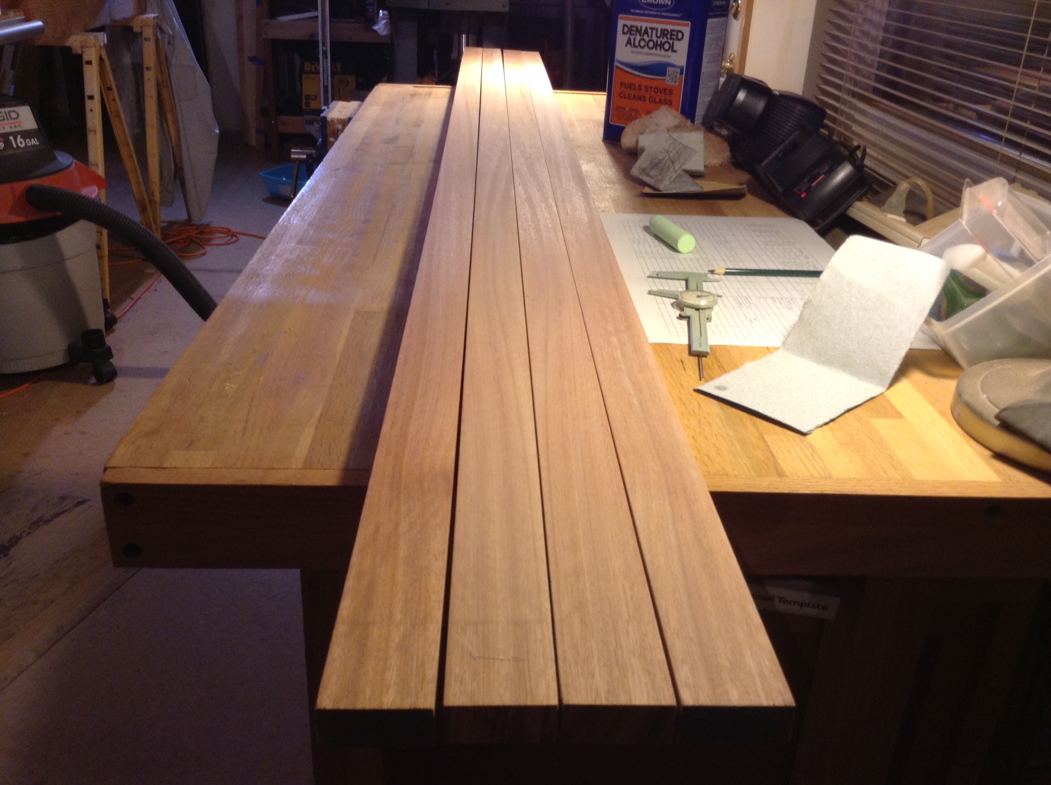
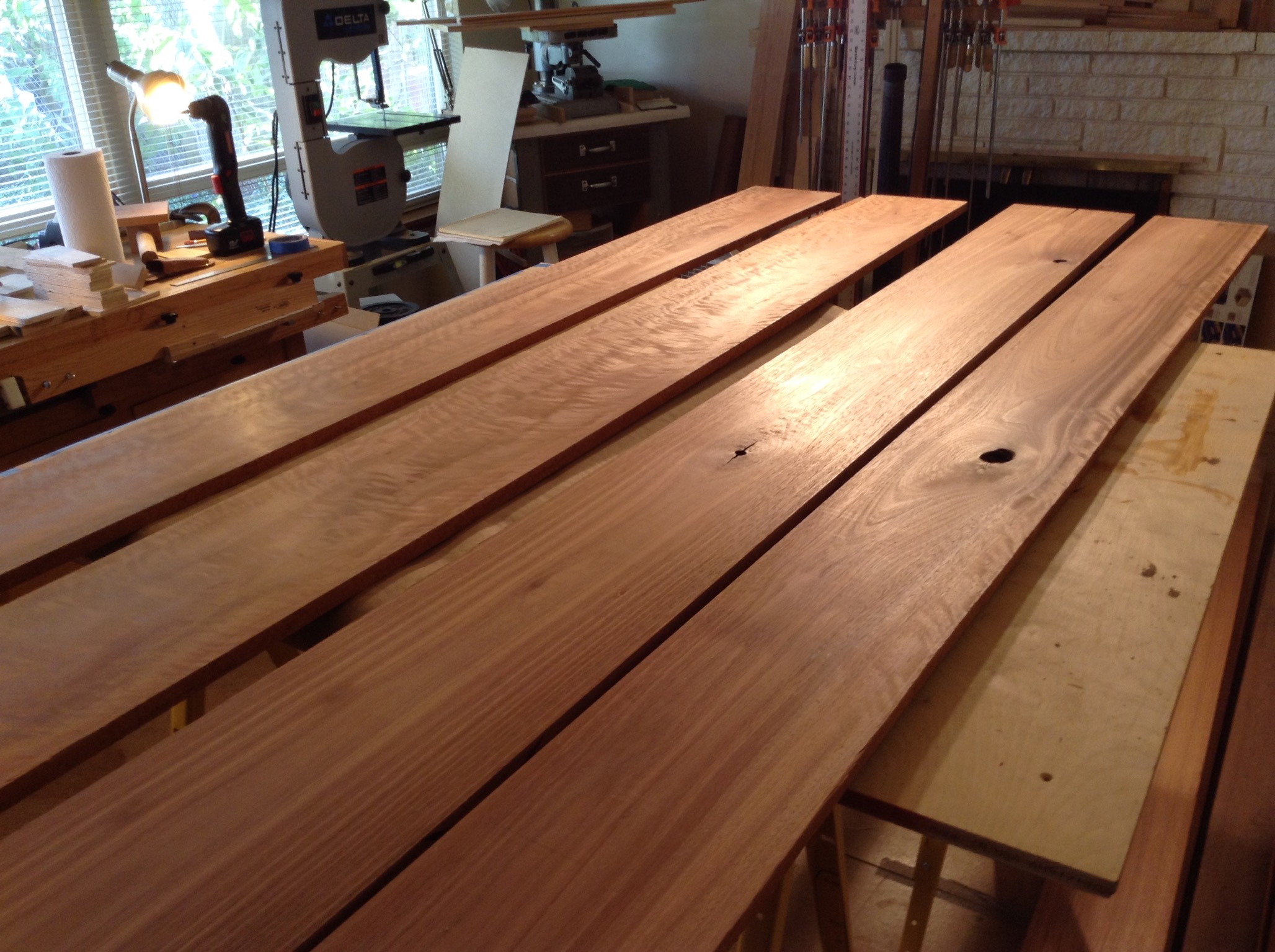
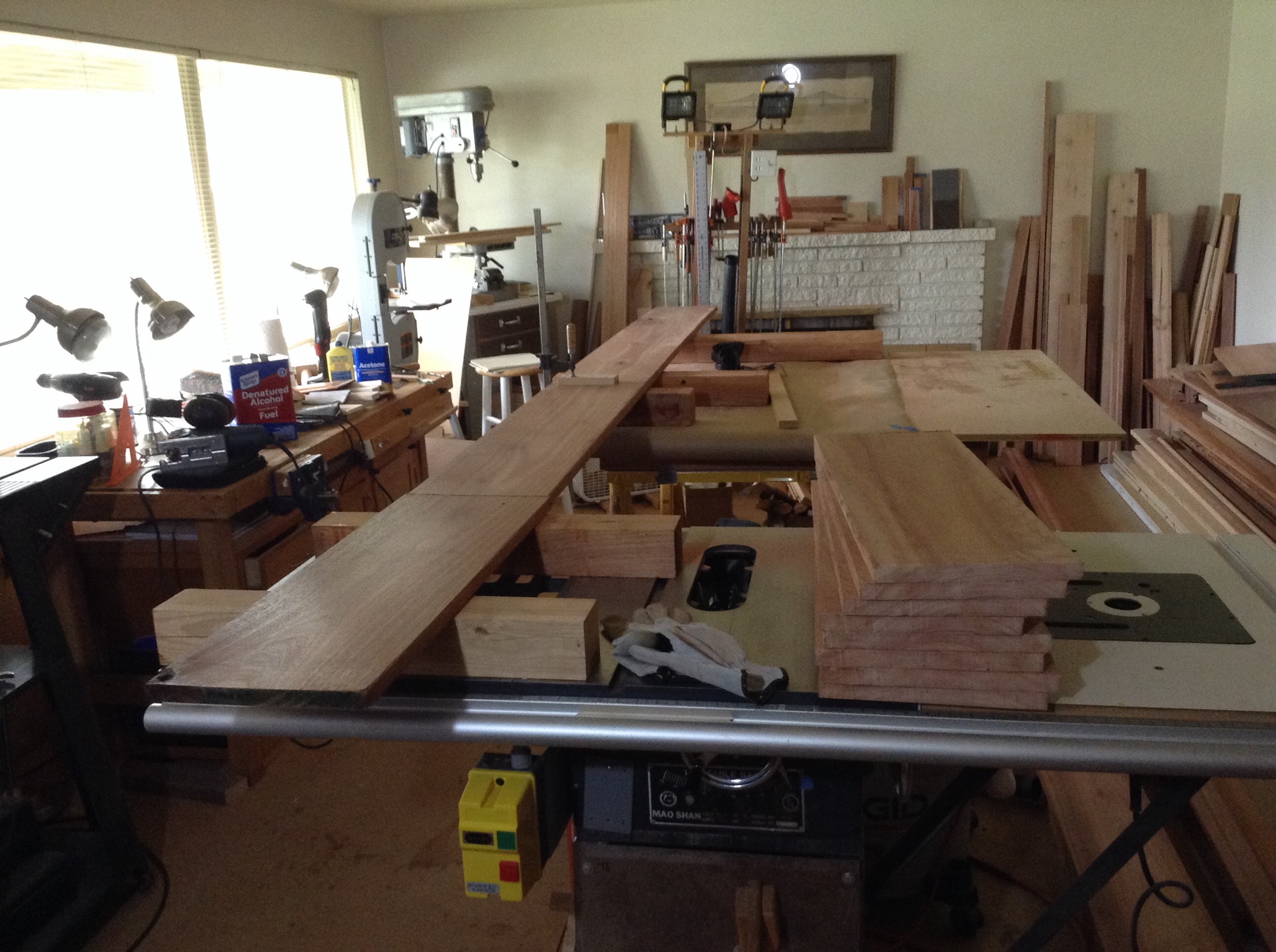
Selecting Wood for the Floating Panels and Initial Crosscut
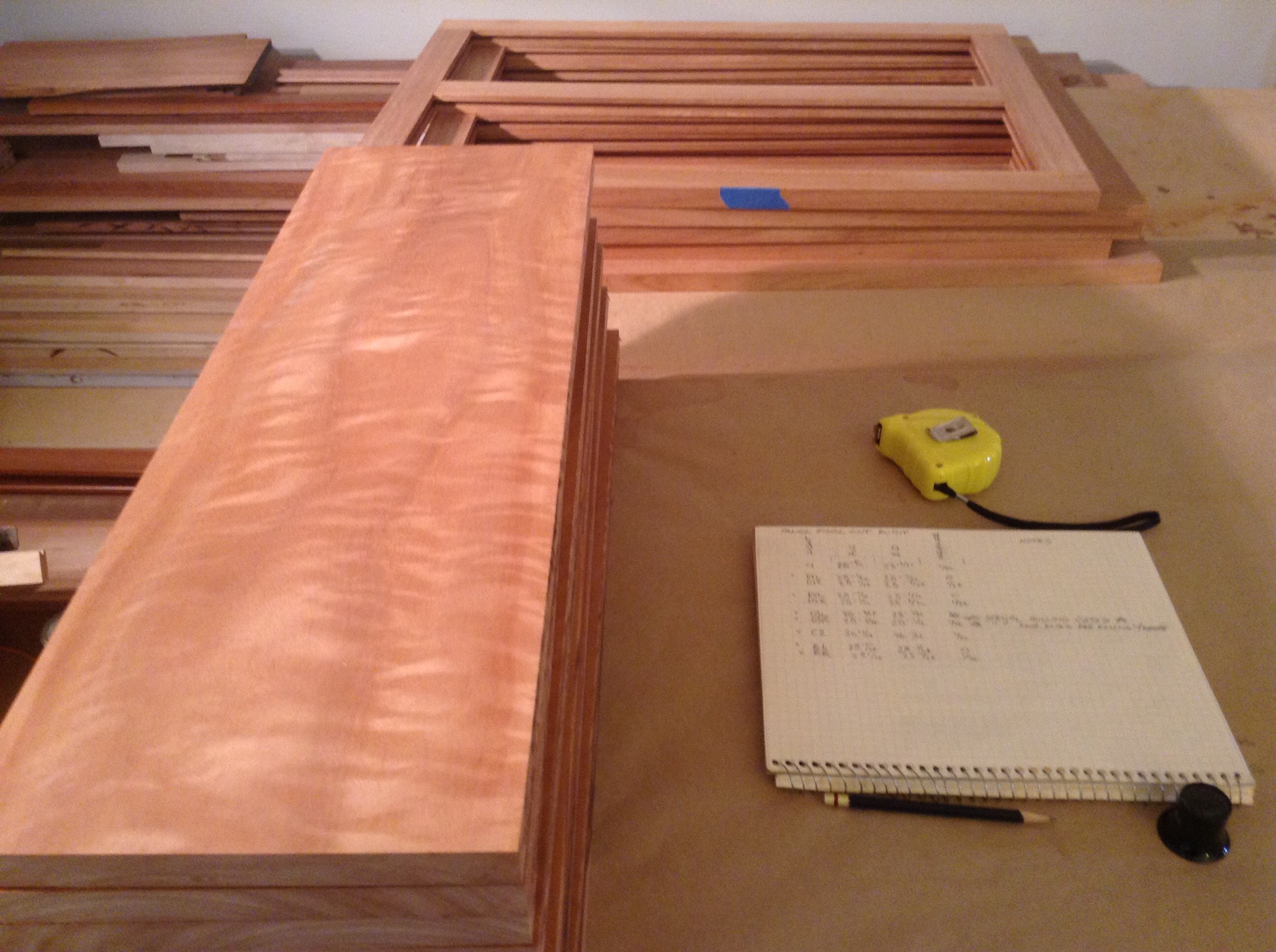
These are the four boards I'm considering. To do the eight panels on the back side (what you can see on the above picture) it will take any two boards. If I'm looking for a selection of similar panels I would use the two on the left or the two on the right because these pairs are each from their same tree. The two boards on the left are highly figured showing extensive saturation (90%) of spiral and reverse spiral ray fleck. These are real special boards and this cabinet would wear them well. What a splash it would be having eight figured panels, from the same tree and nearly consecutive flitch boards filling this group of eight adjacent frames.
But before I get 100% sure on this decision I must consider the next project. The next project is the hutch. So should I save these boards for that then use the two boards on the right, that are great in their own right even though the three open knots need to be dealt with, for the peninsula panels. For the knot holes do I cut them out or keep them. I could fill them with black or metallic epoxy. Maybe turquoise (I've see this in Taunton's Fine Wood Working) or use some another color like brass to match the cabinet hardware? Black will always work but I would prefer 1/2" or less diameter holes for black. Two of the holes are bigger than that. So I have decided on a metallic flake. Probably brass to keep from adding another color to the mix in such a bold way. I've checked out three places and I'm looking a $100 just for the epoxy and dryer. Pricey so I have reason to avoid filling holes at this time.
:
The four wide boards.
:
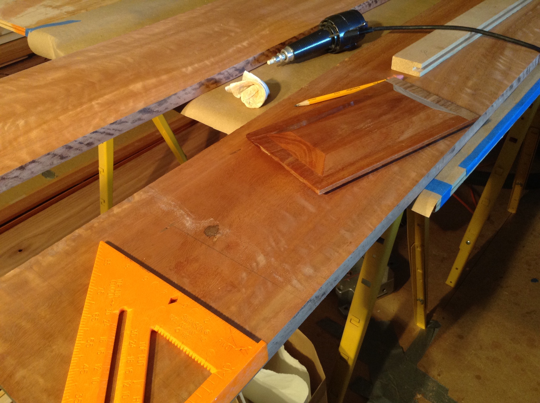
Marking Up.
The process of marking is a serious one for me. I find a draftsman's electric eraser works real nice with gummy erasers on most woods. I also use it as a burnisher with a gritty eraser. For a final markup I use a much better square. The mill sample of a tongued panel is used to help visualize what material will fall away during the milling of the tongue. For instance, a knot should be outside the milling zone of a tongue. Either in the panel proper or cut off and not part of the panel.
:
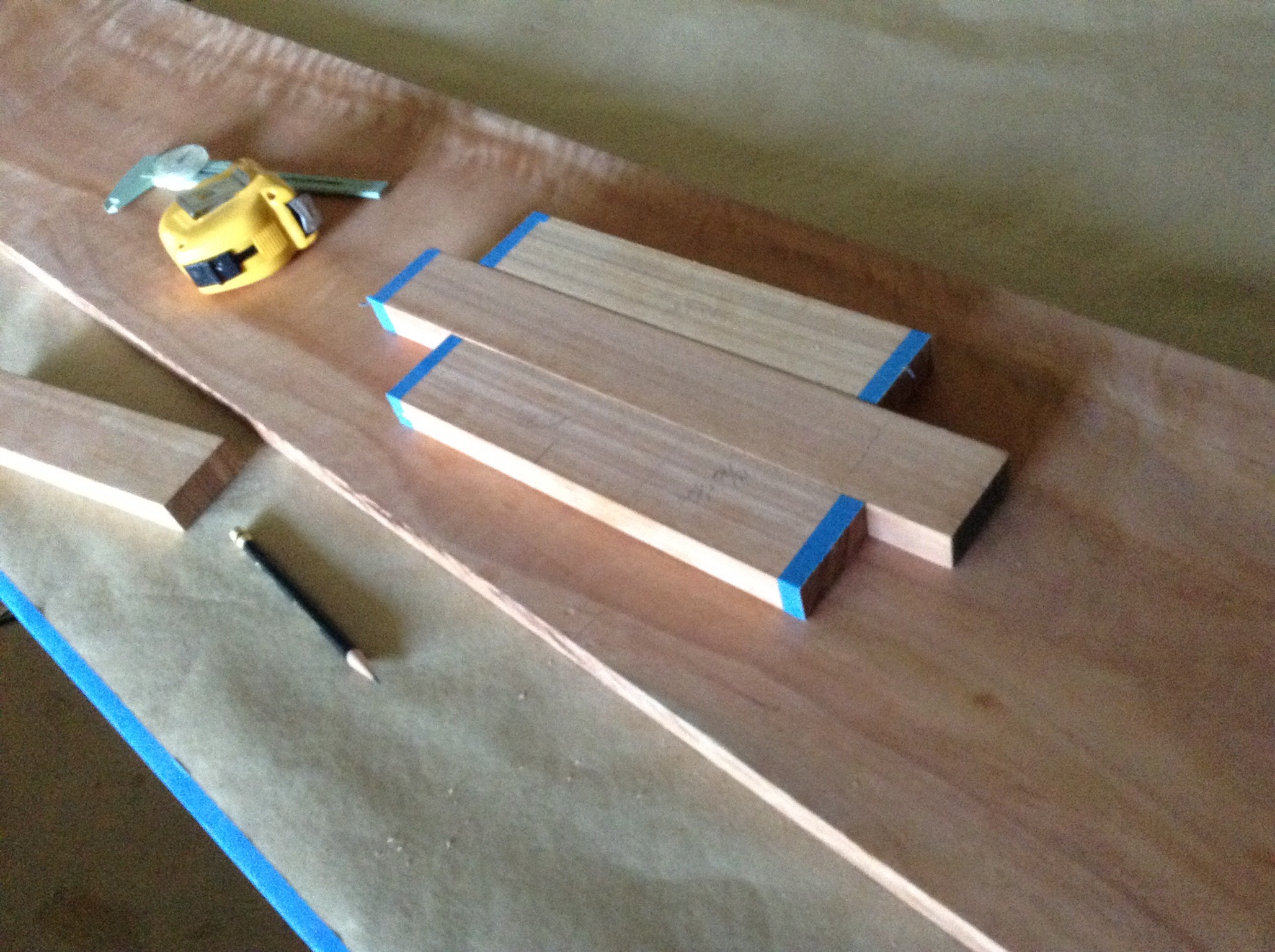
For the hutch planning of the oversized rails: If three quartersawn lyptus boards were glued up like this and then ripped 2-1/2" from the outside I will only loose 5/4" in the middle as sawdust and trash to provide the two 2-1/2" boards needed.
:
For the peninsula panels The seventh initial (rough) crosscut operation completed. I'm using the Bosch 1590EVSK jigsaw for this. The front steel plate of the Mao Shan at the bottom of the picture just below the Up / Down Blade Height Wheel comes off later for the arbor adjustments.
:
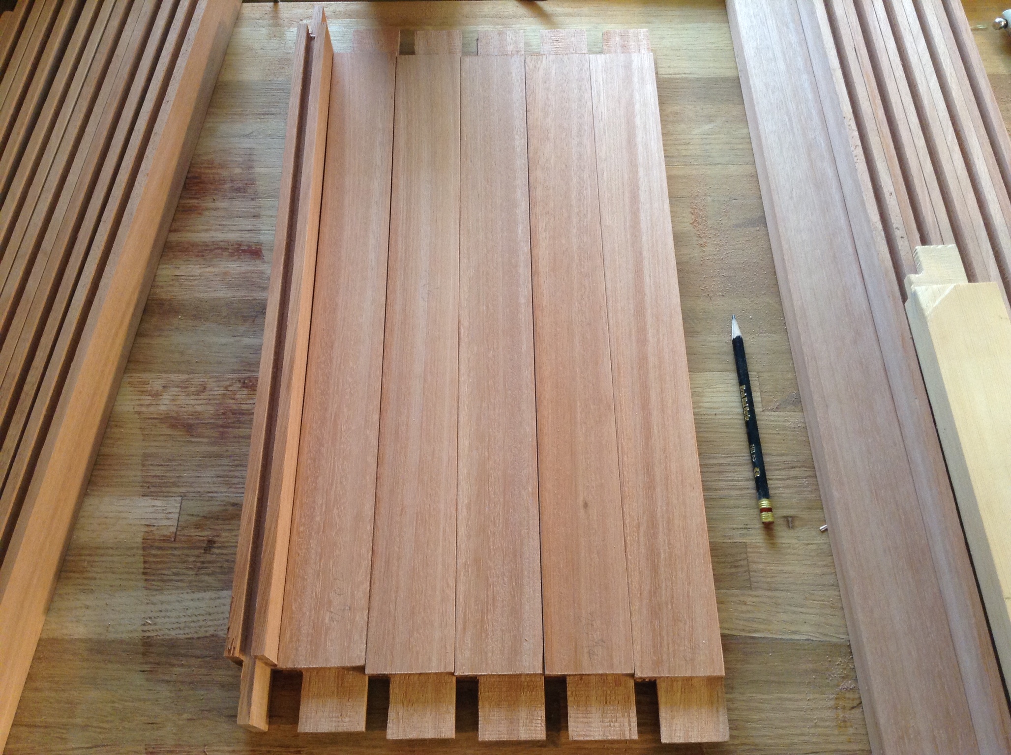
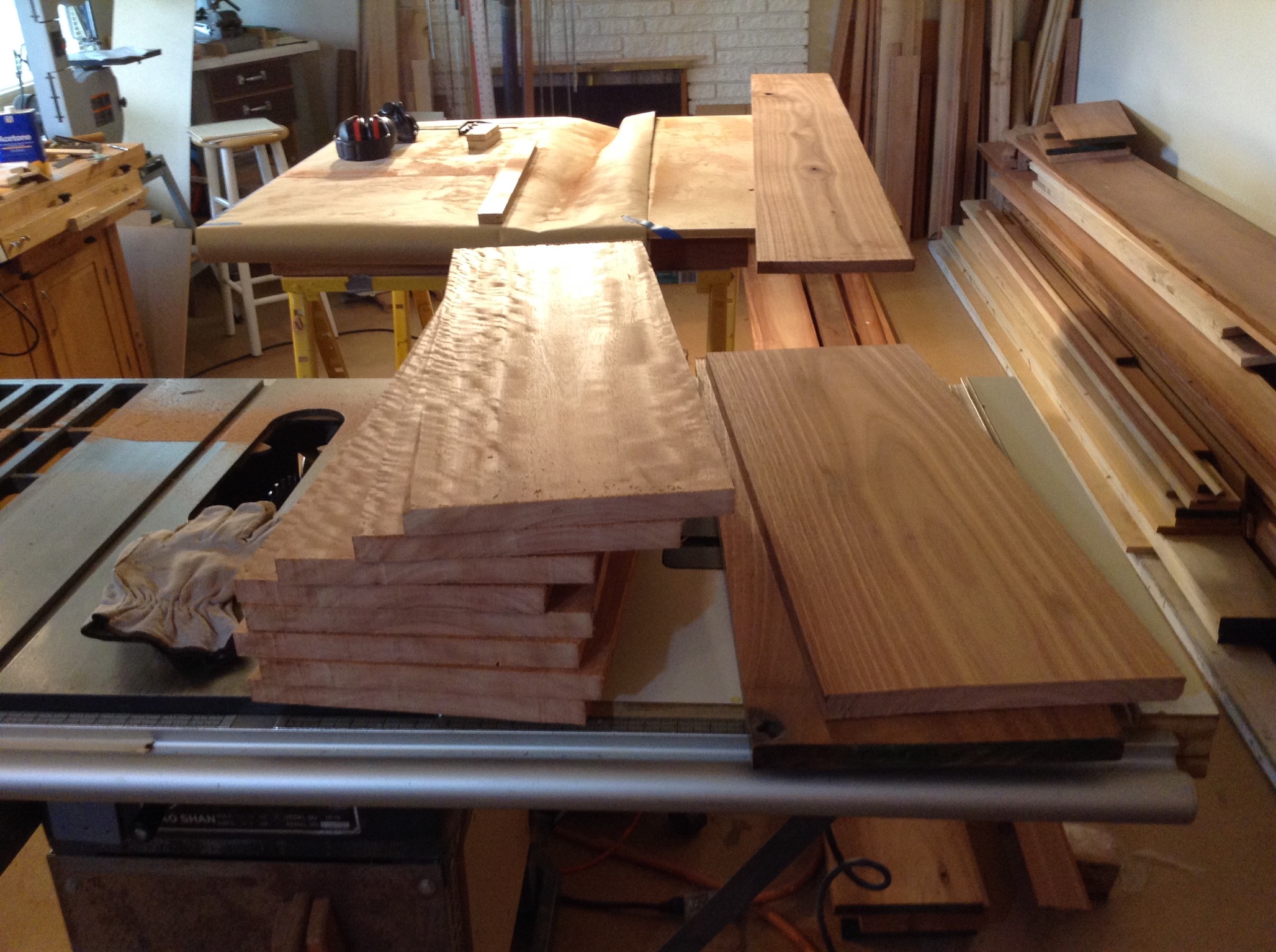
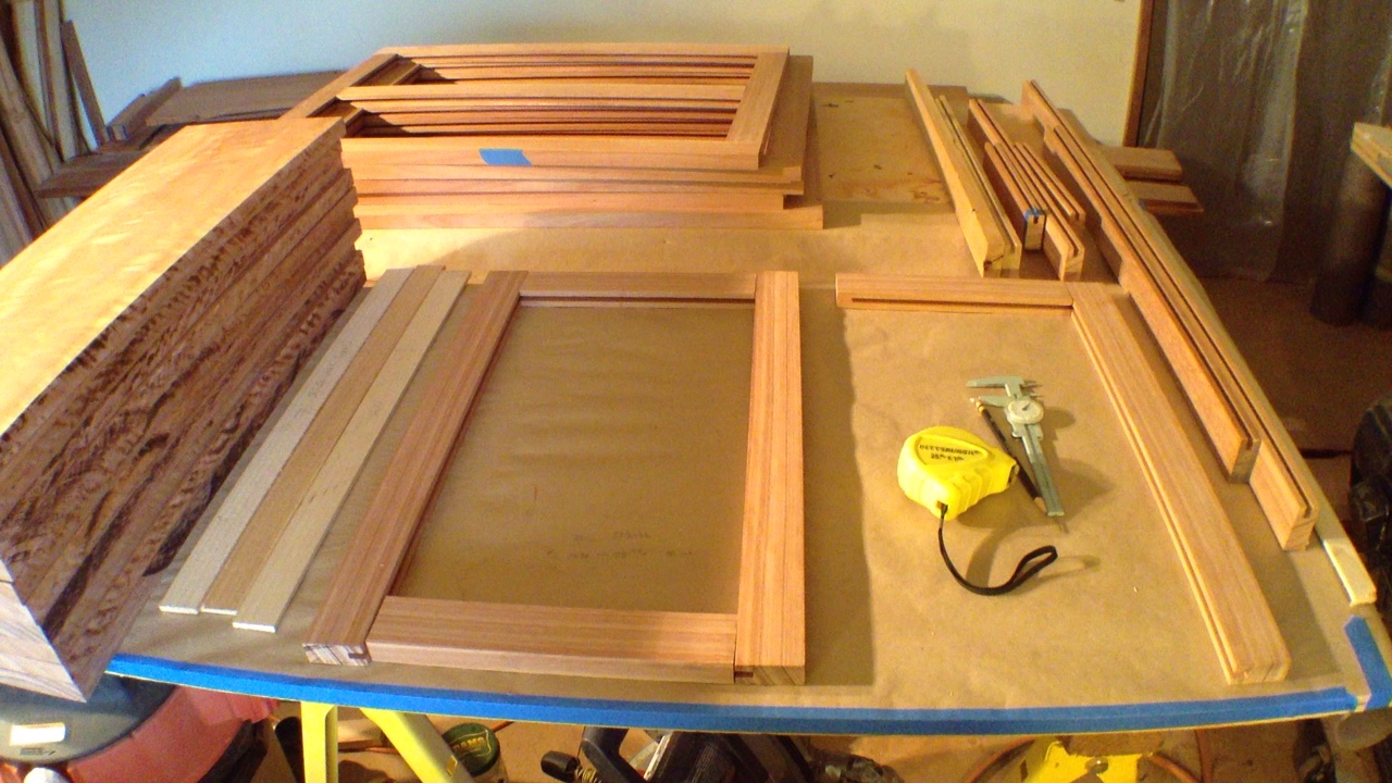
All the Initial Crosscuts Are Done
Look at the figure of the stack on the left. It is a big wow! These will go up on the outside of the peninsula cabinet. The two stack on the right will go up on the peninsula end. I flushed these with alcohol to see what the end will look like and they are spectacular too. They show real depth and richness. Comparing the two you can see that Weyerhaeuser is using multiple mothers for their clones. I could get everything from light salmon to dark red. I'll be using the sawdust soaked in alcohol for each color and straining out all the particulates to use as some of the alcohol component in the shellac sanding sealer layers. Each of the shellac layers meld together and four layers can be applied as a real thin coat prior to the one or two polyurethane layers as the top coat... I'll be using three color derivatives, bloodwood, salmon lyptus, and van dike brown lyptus alcohols with de-waxed shellac. So I'm using more alcohol than shellac for each flooding of the surface. Just enough shellac to create physical separation with a higher layer. The water base poly layers could be blends of or blended coats of clear and satin long molecule urethanes. I tend for more clear that satin on the figured wood. I'll need the color treatment with the shellac to counter act the blue added when using water base polyu's. With mild soap and water only cleanup the surface should be fine for 50 years.
:
Calibrate the Table Saw
The table surface opening in front of the blade opening got out of flat because the bolts in the horizontal piece got loose. So I re-flattened the surface and tightened up all the bolts. With all that banging around its time to measure and correct; blade and miter slot at 90, any blade runout, and perfect the blade to table 90. Here the top has been deep cleaned and the blade cleaned. The top needs treated with a Empire Top Saver, If I can find some, to reduce the coefficient of friction to reduce slide chatter. Then calibrate the 90 on the Dubby so I finally can start cutting the panel blanks square and to final dimensions. I measured the saw blade and miter slot, the blade is out of parallel by +6.5/1000" from front to rear. Access to the trunnion bolts in the rear is easy. In the front not so much. The table top to skirt bolts are 12mm. The trunnion bolts are 1/2". I loosened up the rear trunnion bolts and re-tightened. I dismantled the front sawdust plate and must do the same on the front trunnion bolts. Need a extension arm for the ratchet wrench. Then I'll loosen up three and start tapping with a rubber hammer and measure the results to 1/1000 of on inch. That's crazy, in a Monte Carlo beat the house kind of way, but it's got to be done. I'll be satisfied within 2/1000ths plus or minus 0.5/1000ths of an inch.
:
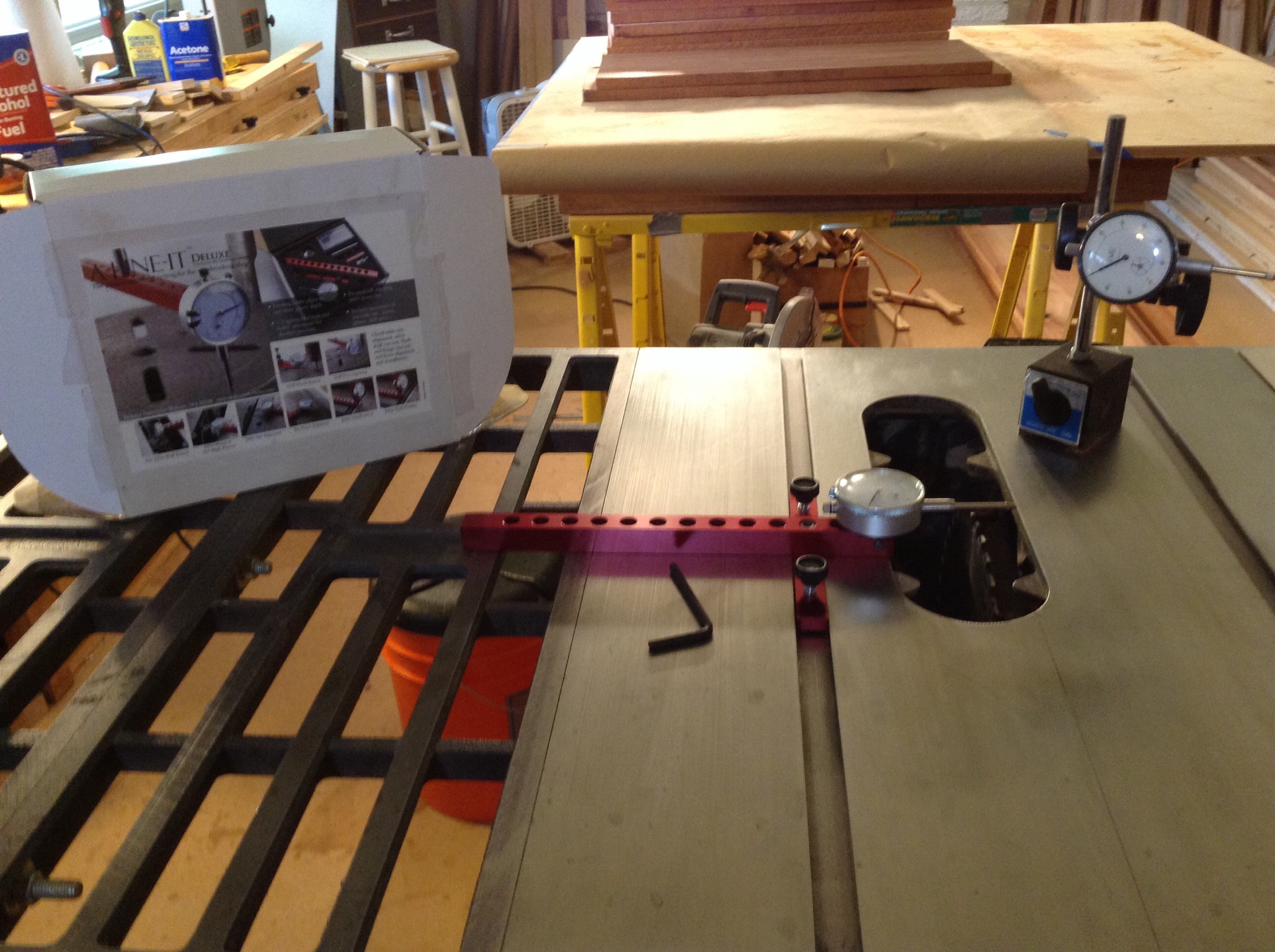
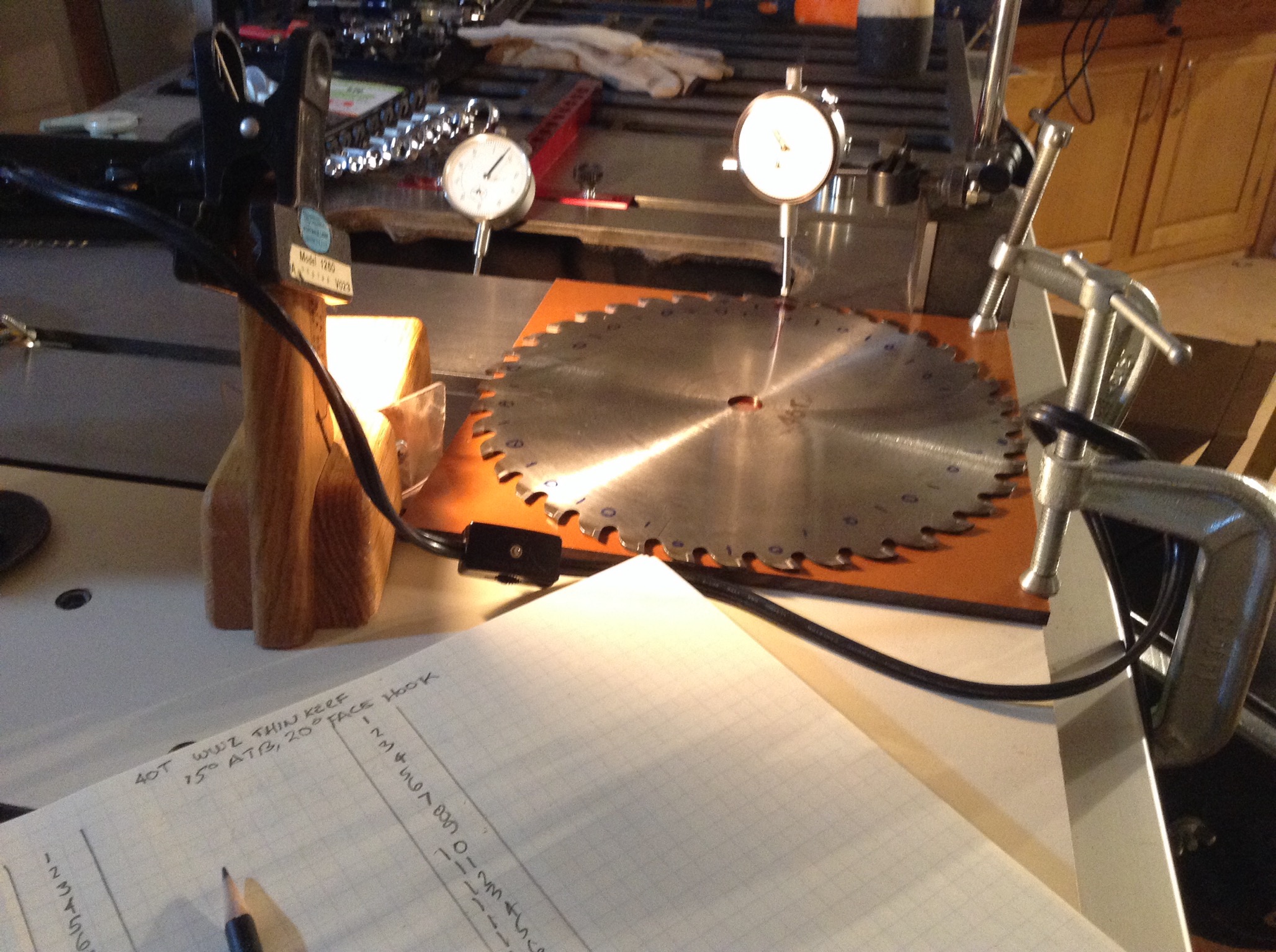
Arbor Flange and Saw Blade Flat Measurement Setups
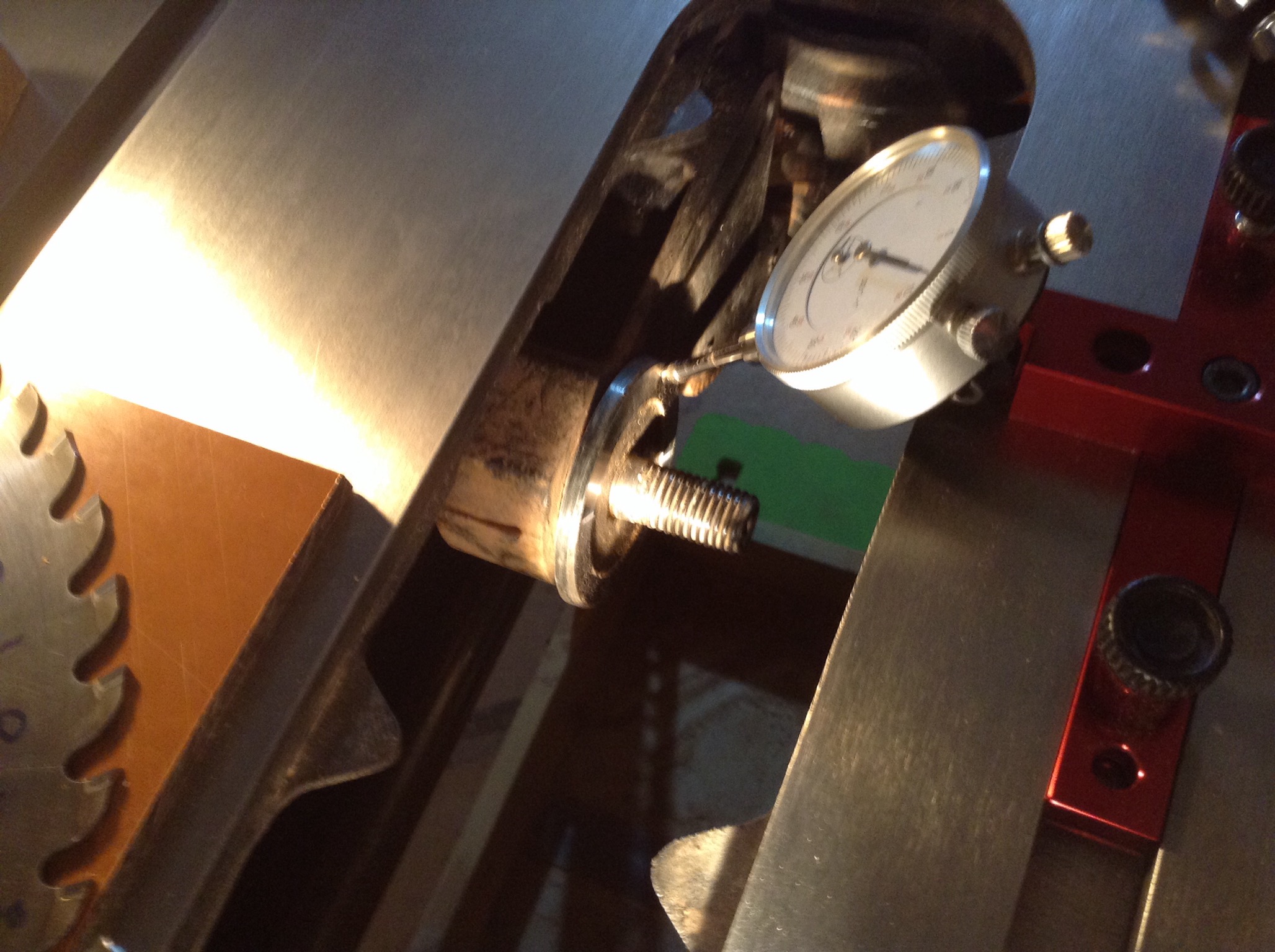
Click on this picture to download the full picture then zoom in to the width of tablesaw top. You will see in the center, two high quality Plunger Dial Indicators, PDIs. Each one is calibrated to 1/1000's of an inch both also have a floating zero function. The arbor's attached flange is 2-1/2" in diameter and I can only read back and front of the flange just above axial top dead center of the axle. The setup tool providing structure for the attachment of a PDI is the A-LIne_IT Deluxe. I got mine from Woodcraft in South Seattle. The saw blade will be measured radially to the cutting tip of each blade tooth. I'm using the Forrest 40 tooth, thin kerf of 3/32 with ATB cut carbide tips ground to specifications for each blade. Both operations are done with just one gauge setup. I'll have the blade offset inputs imported to Autocad2000. These will be CDF z, y, & z acad line of text command per radial point matrix of tip of tooth and on the flat as close to the bottom of the tip as I dare for both the each side of the blade body. I'll be able to plot them in 3D in autocad and then fly thro this topology inspect the out of alignment issues. I know this won't bring me any useable results for several reasons. I just think this is fun. There is a broken carbide tip. It doesn't seem to deteriorate the overall quality of the cut. So I'm looking for more errors to justify sending back to the factory for alignment and tip replacement or the purchase of a new blade. In my world alignment would be spelled alignment. Anyway, I have Blade # 99928! Under the blade on the table saw is a phenol sheet. It's a 10" x 10" x 1/4" thick sheet that it is primarily only good for tooth edge measurement not the flat so much as the carbide teeth rest on the test measurement surface. When the blade is centered four teeth are mostly overhanging at 12:00, 3:00, 6:00, and 9:00. I raised the blade off the phenol sheet using three niobium magnets. As I rotated the blade on the axis each measurement of the tip edge was shot with camera, and then I input the photo information into Excel, and on to Autocad. The pole meridian for the 12 midnight tip is marked out on each side of the blade acting as the registration points. The blade teeth are counted as 0,1,0,1,0,1... Odd and even. Highlights at 0, 90, 180, and 270.
:
Plunger Dial Indicator
Courtesy from https://www.generaltools.com/economy-plunger-dial-indicator
The picture of the General PDI below is an example of some really great photography. One of the things this photographer used was a light block out disk to prevent light glare on the crystal like is evident on the bezel.
A lot of woodworkers rarely use tools with this accuracy. I need to use them to know what I got to do to be able to get the best cut I can. I may have a few issues with the blade and the flange. I'm going to find out.

:
The PDI Setup for Arbor Flange, Front and Rear measurements from the miter slot., at just above top dead center. The TDC is measured as constant if the 0, 90, 270 agree. So the arbor is spun slowly reading this circumference of the TDC test point to look for undulation or warble. The second test is for the blade flatness. Blades get out of flat when overheated and or have had long use. I have got a lot of wood cut with this blade and it's time to take a close look. My rips have been burning although it is an under powered blade and the rip fence setup for big, thick, hard, sappy, and long cuts. This setup is measured from the right of the blade to the rip fence for alignment so does not use the miter slot as a registration point. Good alignment for cross cutting and short ripping to square the panels I'm getting ready to cut is done on the Dubby so the miter slot is the registration to calibrate now. It will help reduce wear on the blade too. A lot of pitch needed to be scrubbed off the blade and carbide tips. The expansion cuts in the blades needed a cleaning with a diluent and some tooth floss to clear the four question mark shapes out.
:
:
Trunnion Bolt Access Continued...
After due diligence & tool purchase.
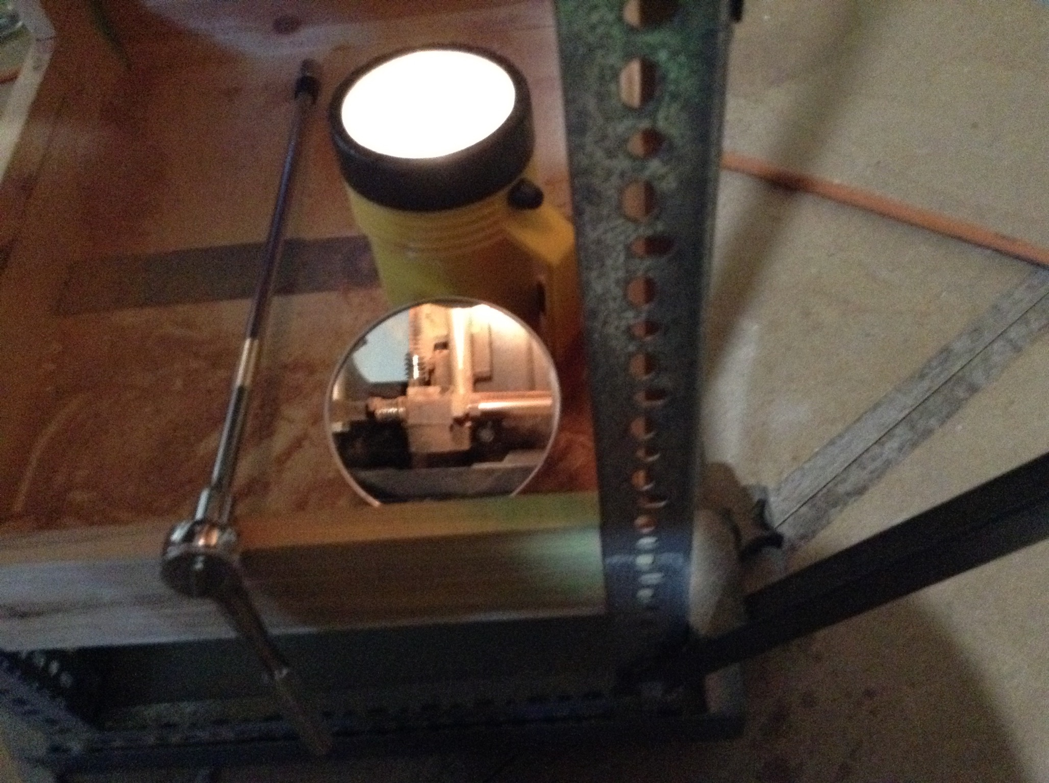
Looking down to see back up through mirror into the most tightly confined space of any trunnion bolt.
The right front tight corner trunnion blot head access made easy with a lamp, mirror, and 18 inch extension arm for the socket ratchet.
++
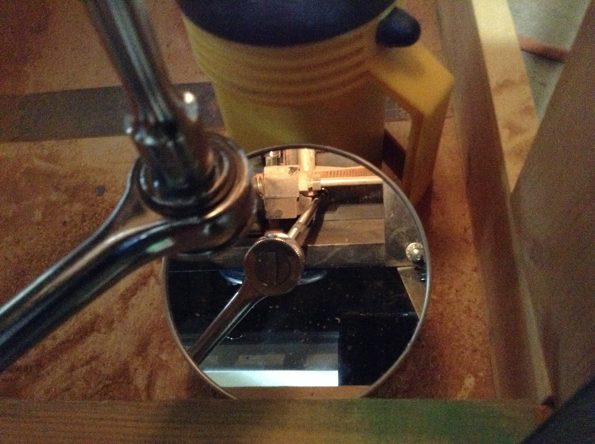
Trunnion bolt head connected to 18" socket set extension arm seen through mirror with flashlight while sitting on bucket in front of Mao Shan Table Saw with positive torque pressure twisting and upwards. One hand on wrench and one on the iPad. This is an easy working setup that doesn't force me to pull the sawdust floor out. Because poking my oval head, into the square opening, trying to see up through compound glass lenses, and manipulate a socket set, was very difficult with the sawdust floor I installed. While it's technically a cabinet saw this aspect, the sawdust holding cabinet, was not resolved in the original design. So any dust control cabinet must be removable to allow access to the front trunnion bolts. It is to some degree. To get to access this space four bolts, nuts, and star washers need to be removed to pull off the steel sheet panel. I discovered that eyelets in lieu of hex dead bolts along with washers and nuts where the nuts are on the outside works best. I can install them with my fingers and one socket wrench after removing the wood left and right panels, washers, and nuts. For this setup accessing this right front trunnion bolt takes me about four or five seconds to take the ratchet set and be in a positive torque force mode each time I do it. And sitting comfortably on my old Duluth Trading Bucket Top Seat Pad while doing it is worth it. I think you can get the bucket top seats now through ACE, Amazon, Home Depot. I had to put out cash for the Socket Extension Arm. I had to buy a set of four for under $20 at Harbor Freight to get this. I don't think the 18" ext. arm will ever be used for anything but this.
:
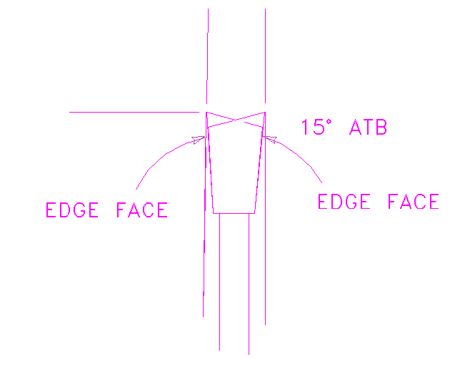
Edge Face Measurement Sketch
Sketch shows two tips overlaid to illustrate their opposition ATB (Alternate Top Bevel) at 15 degrees. Carbide Processors Inc has very good technical information to share with us. The 15 degree ATB is a good cutter. Not so good a flush cutter. It leaves friable fibers at the bottom of a trench. When I use it for a through cut I like it's minimal tearout tendencies. When I do use it as a trencher? When I'm using the Dubby and I'm milling material off both sides of a rail when creating a tenon on the ends. I prefer milling perpendicular than cutting the line by holding the rail vertically and moving it through the saw blade. So when I use this blade for narrow milling I must stop at the correct width then I knock off the loose fibers with some sandpaper to create enough space for the thin film of glue as well as the cleaner glue surface.
:
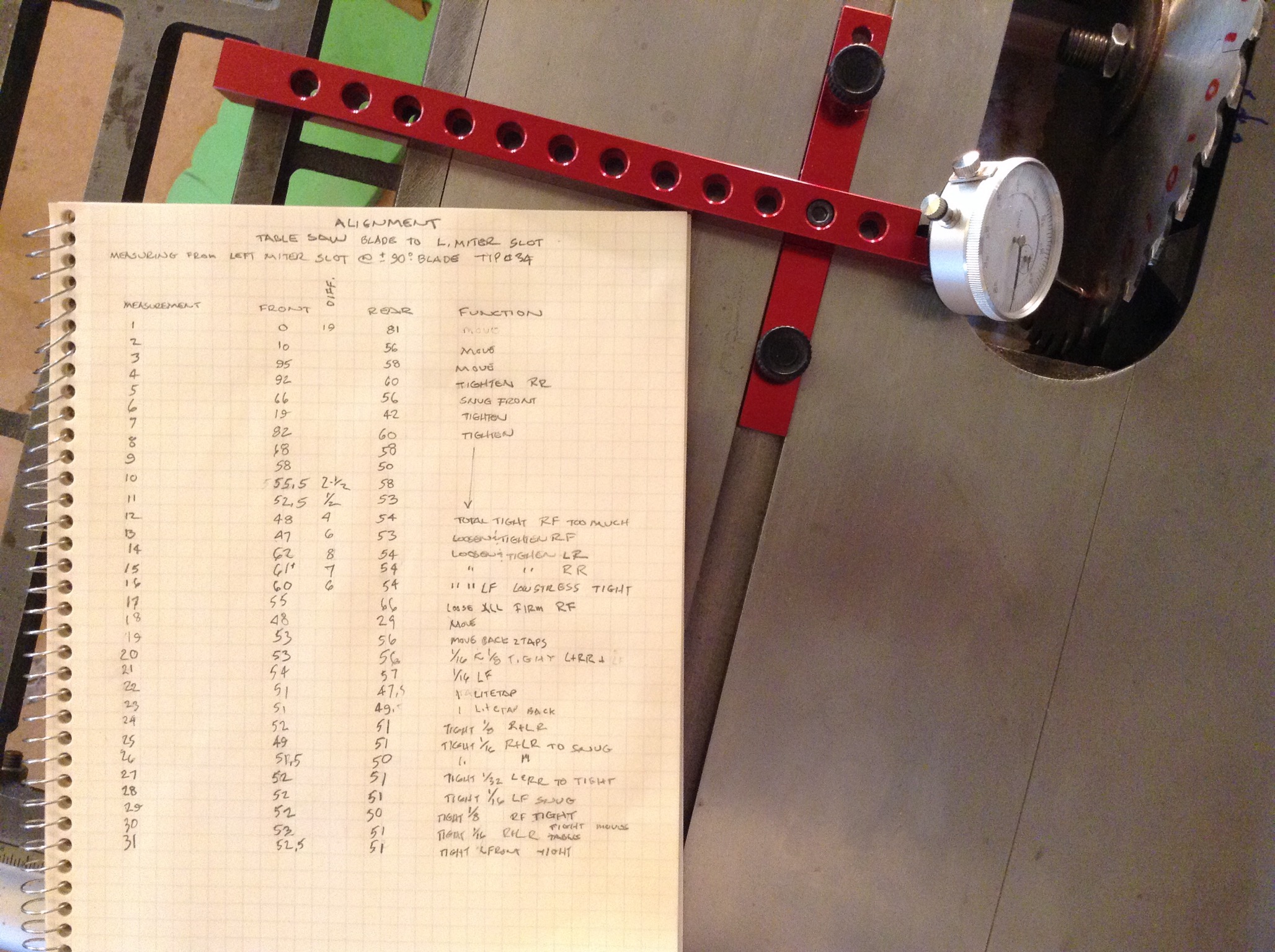
Table Saw with Blade at 90 Degrees - Alignment to Miter Slot and Tighten Trunnion Bolts.
All four trunnion bolts were loosened and set easy. From this loose state to a tight bolt state it took 31 operations to arrive at a one and a half thousandths variance. When I first got close on step eleven, then lost it when I finished tightening on step twelve, I didn't get worried. I did consider how many complete loose starts I could end up having to do. So my first math was using a dim idea of an algebraic equation to connote the repetition of; (loose starts=x) so then, x to the nth power. I didn't like that... so I changed trajectories. I started an x pattern cross bolt loosen and retighten operation. I figured all of the bolted trunnion sections were under deforming stress and I may be able to move or release this stress by doing this. What I learned. First, getting tight out of balance creates torque tensions. This is not good because the next alignment step is to move the blade to 45 degrees and measure. Any corrections at 45 degrees requires shims between the underside of the table and the trunnion. To do that one bolt at a time gets loosened and a shim installed. If there is torque tension then when doing this the 90 degree adjustments goes automatically out of alignment. Not good. So, Second, its best to start with a minimum variance. I moved on to a second loose state at step 17. My theory was then to tap to alignment as close as possible and then tighten in very small increments tapping as needed. By step 31 I'm afraid to touch it as it might go off.
Now on to the next step. Is the blade still in alignment with the miter slot when the blade is at 45 degrees to the table top?
:
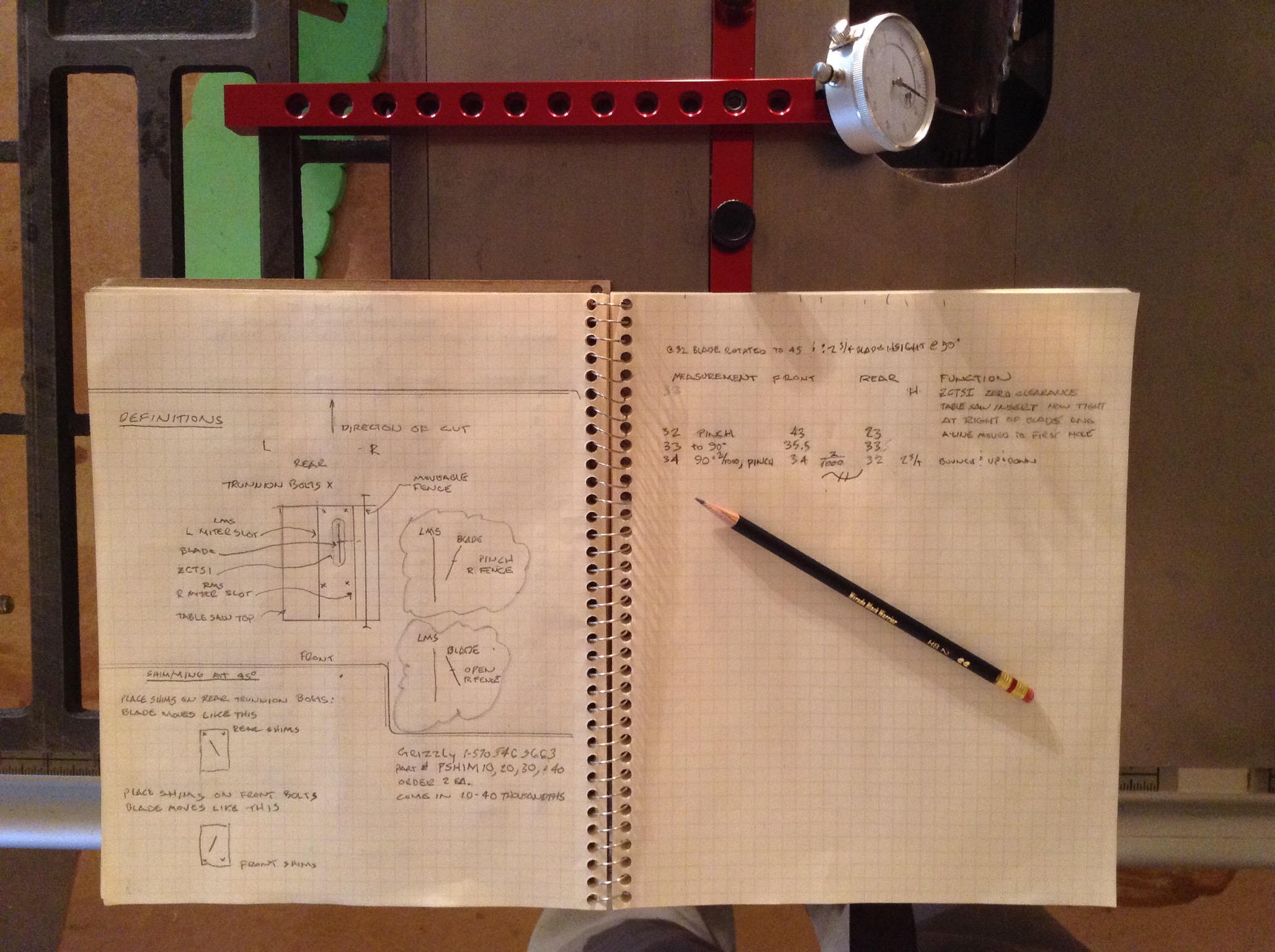
Table Saw with Blade at 45 Degrees - Alignment to Miter Slot, Shim Placements, and Tighten Trunnion Bolts.
Continuing the step numbers on page 2, starting at 32, where the blade has been rotated to 45 degrees. I find I can't go further without parts. The variance is twenty thousandths. Not good. So, shim sets are required. I'm not cutting at 45 in the near future, panel component cuts are at 90 degrees, (even the miters,) so I can reset the blade to 90 degrees and re-measure. Step 34: I'm still at two thousandths after setting blade to 90 degrees then running the blade up and down a few times. Two and three quarter inches of blade height is a trusty amount for this saw. Measurements show that changing the height may produce non-parallel measurements that vary widely. So I ended the notes with the swimming man. Now I can plug in and start cutting. Page 2 on the left starts with a Definition Drawing of the table saw. ZCTSI= zero clearance table saw insert. Below that is a set of Shimming Instructions and part contact information through Grizzly Tools. See YOUTUBE 2013 Video. They now sell in packs of five. The part numbers are PSHIM020, 030, 040 and the ten thousandths are no longer available.
:
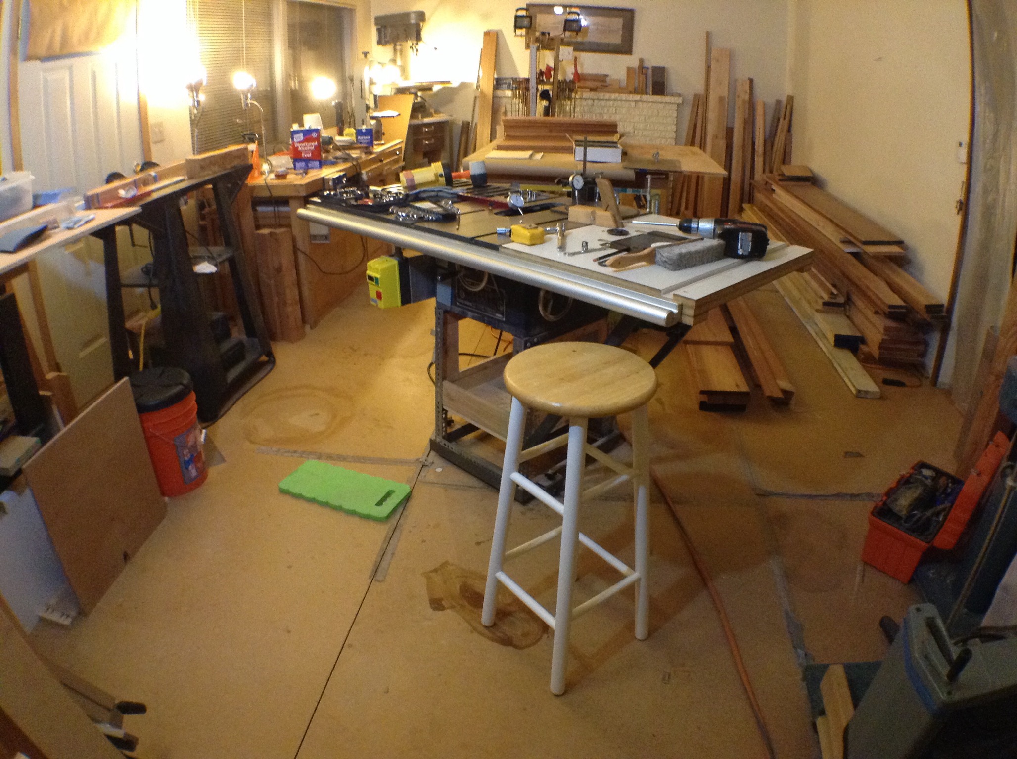
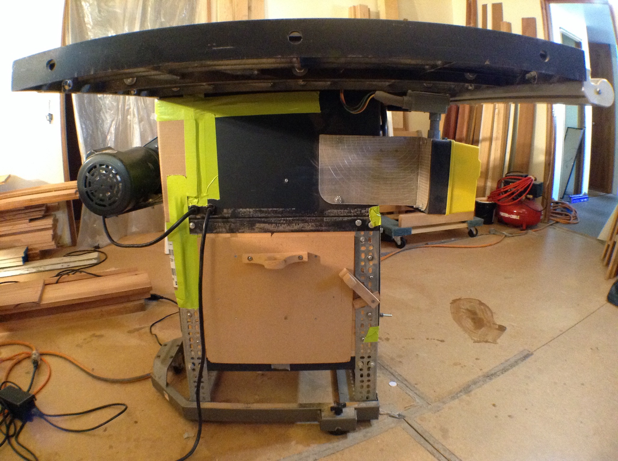
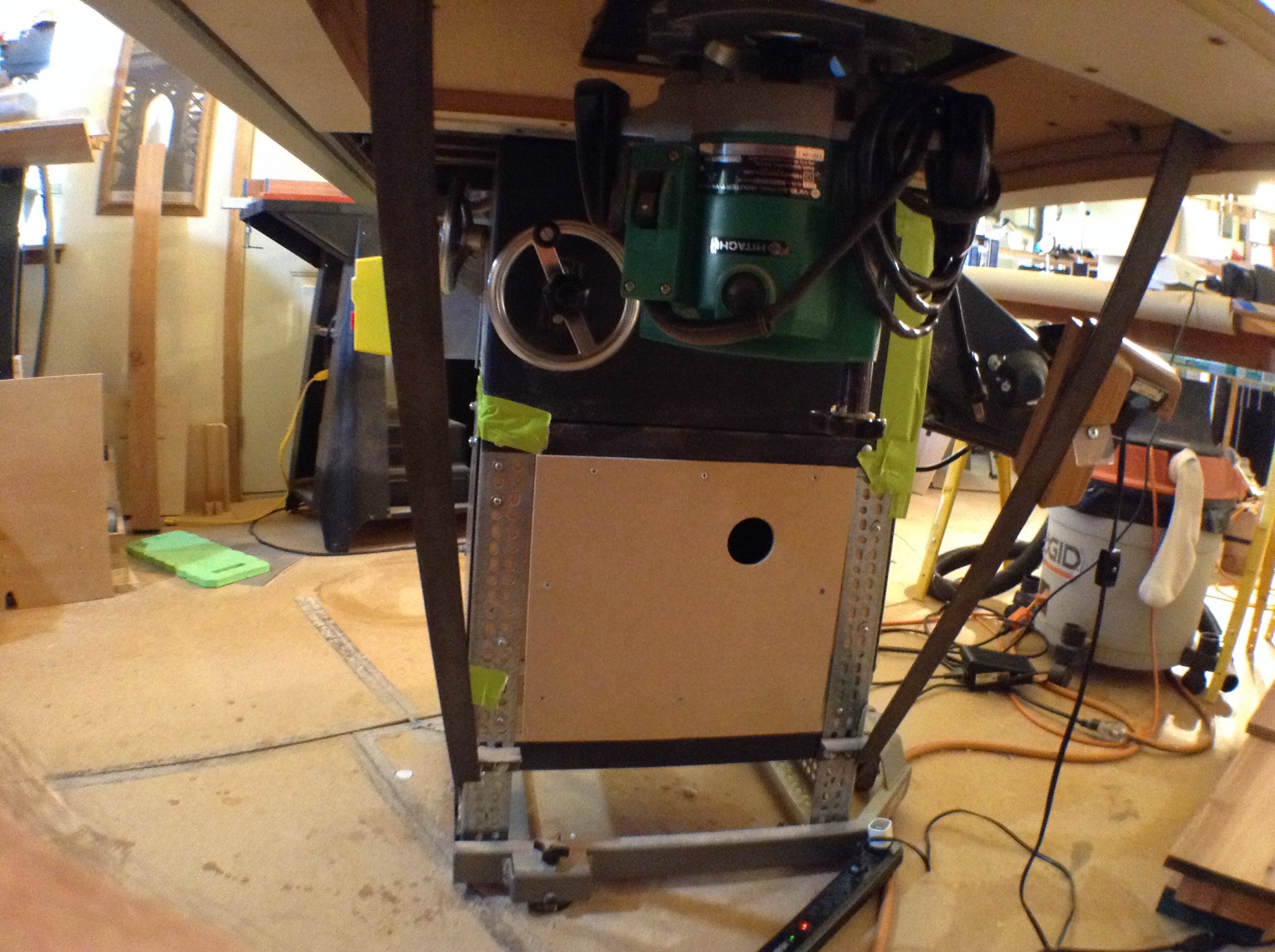
All the Table Saw Cabinet Panels Re-Installed
This tape will come loose and need maintenance. Got to get more day glow tape. Tape helps create a vacuum to suck debris down from the top. Or at least keep them in the box. I'll do some testing to maximize this sucking action I'm looking for. The give away zone is just under the top. There is a gap that can't really be blocked. The suction should still have enough power to pull down dust around the ZCTSI and it's finger hole.
Table saw cabinet, left side, cleanout hatch, with Green Apple tape. 2018.
++
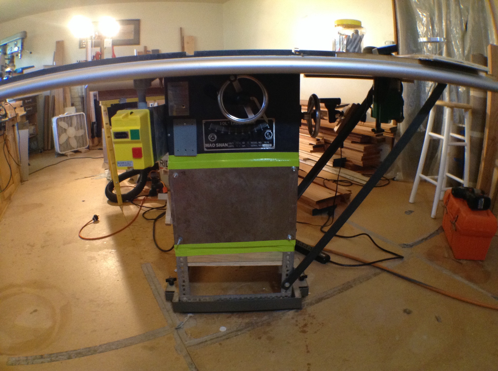
Table saw cabinet, front, with Green Apple tape. 2018. The sheet metal had begun to rust on the surface. I treated it with a rust inhibitor to freeze the pattern. The red oxide colors are changed to include brown and black overtones that darken and compress the contrast of the patina. Mao Shan looks a bit like a rat rod now. Nice. Custom angle iron supports for the right leaf to support the router. The ON / OFF Switch is replaced with a magnetic switch with the 220 volt rewire of the motor and the switch location is relocated to just flush with the front edge of the aftermarket Craftsman XR-2424 Fence Accessory's support tube and table top and leaf stabilizer. The Cabinet has a dolly with locking wheels. The cumbersome splitter and metal table saw insert have been replaced with a ZTTSI and an adjustable splitter. The cabinet space is enclosed and integrates with the shop vacuum with a static bridge between the two components. Nothing is as safe as a Shop Saw... and this Mao Shan is the polar opposite of a Shop Saw.
++
Table saw cabinet, right side vacuum opening (suck hole), with Green Apple tape. 2018.
++
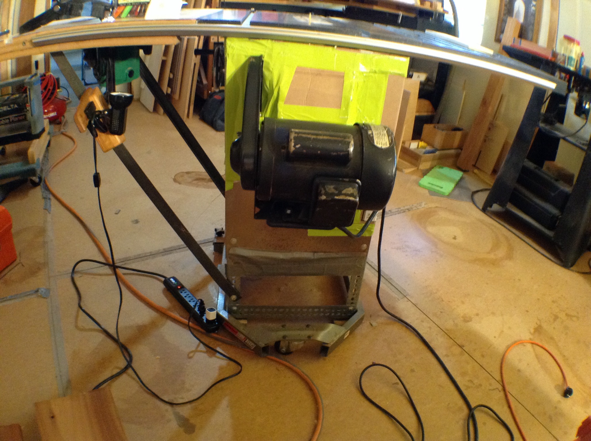
Table saw cabinet, back side, motor mounting bracket and belt shroud, with Green Apple tape. 2018.
:
ZCTSI
I lowered the blade below the top and installed the zero clearance table saw insert, ZCTSI. When I raised the blade it came right up through the zero clearance slot. All that and only two thousandths variance.
Swimmingly.
:
Top Preparation
The top was re-cleaned and lubed. The lube seen here will be wiped down again to get dry. I had to order twice from Amazon to get the Top Saver.

:
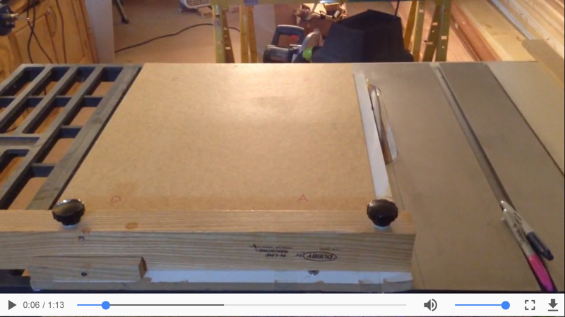
Test Movie
Link to mv4 movie of test drive the table saw with the new adjustments. This is a non-imbedded mv4 movie. That's a hyperlinked snap shot of the player below. The mv4 works best with Apple and Google Chrome. Not so good with IE 11 that uses the Windows Media Player to watch the file. After you have downloaded the movie IE 11 then works on the second watch.
You are seeing the Dubby on the table top with a rectangular piece of masonite on it. I cut three sides of the masonite and measured the diagonals. No variance. The setup is square! I also dry lubricated the underside of the Dubby. Everything is slowly coming together and working extremely well.
:
Lots of Cuts
The floating panels press against 1/4" rubber balls placed in side the stile and rail grooves. If done correctly, this allows the panels to be held firmly in place no matter the wood's contraction and expansion as the seasons change and due to cooking steam which impacts the wood all the time. Test sticks are among the first to be cut and used to determine the dimensions by fit so the Lyptus Milling of the panel blanks will be correct. The season, humidity, wood type, and moisture content must be taken into account when determining the panel dimensions. I'll use the house barometer and the wood moisture meter the day I do the cutting. Actually I'll do it twice. Once for the rip which is the most critical and once for the cross cuts. Before all this the table saw's dust capture box needs to be reassembled, the top surface cleaned, lubed, and test cuts performed. The Dubby must be re-calibrated to 90 degrees. Floating panel test material must also be prepared as this will be used to set up the router milling jig. I mustn't forget to install some sound muffling material behind the washer .
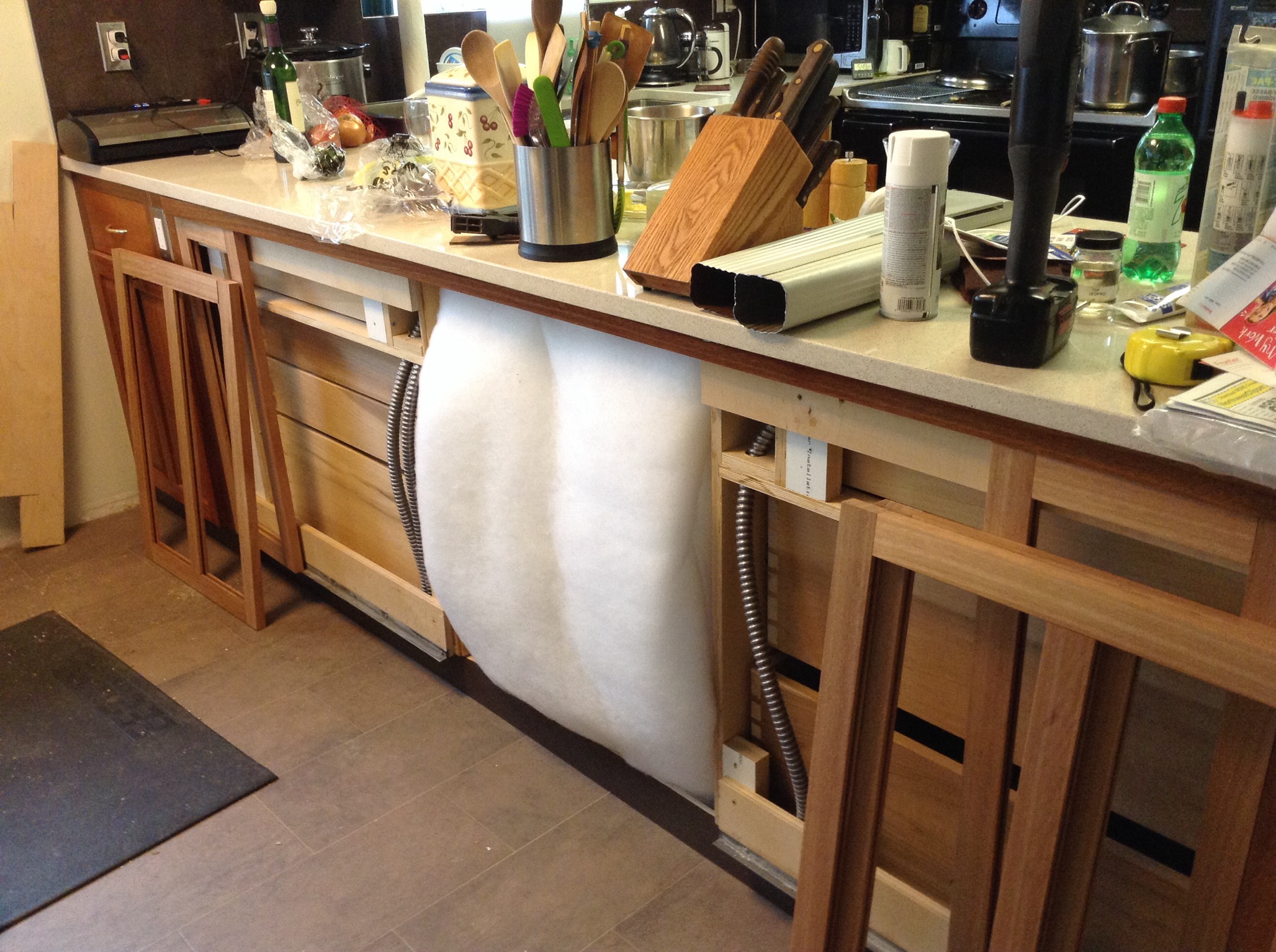
Dishwasher Rear Sound Baffle
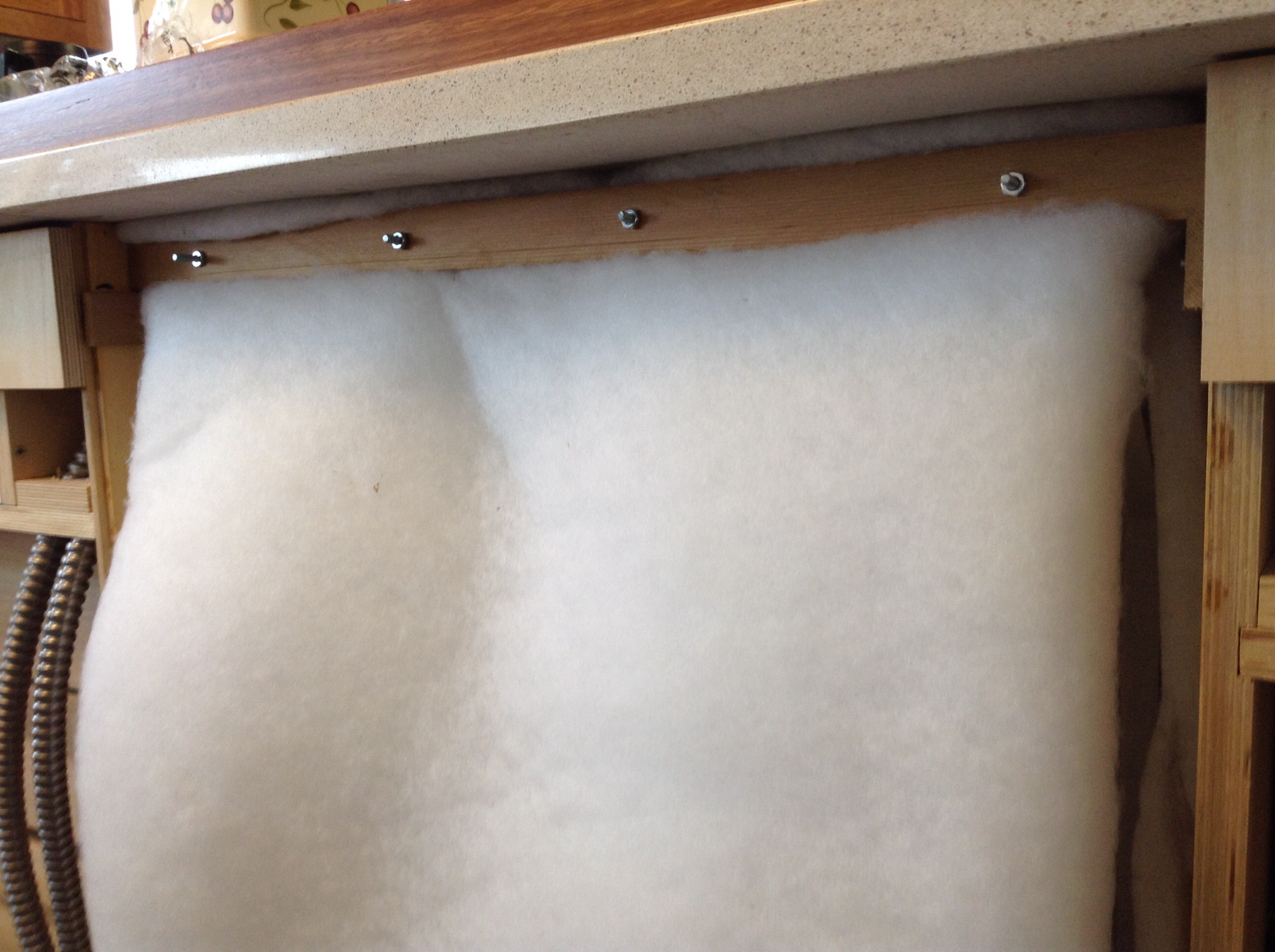
I got the OK to purchase the batting material off the bulk bolt of Joann's lowest cost batting. It fits the criteria; non hygroscopic, synthetic material that won't support mold growth, won't absorb water through capillary action, thick, and a loose random weave.
Welcome to my mess. Cooking vegetable broth today. It's raining. This is it before I installed the cleats. There are four layers of baffle material hanging like a curtain behind the dishwasher. The dishwasher comes with one layer of this type of material on it's sides and top. The material and cedar are light and the sticks have a zero clearance fit so the assembly stays in place without any real connection.
+
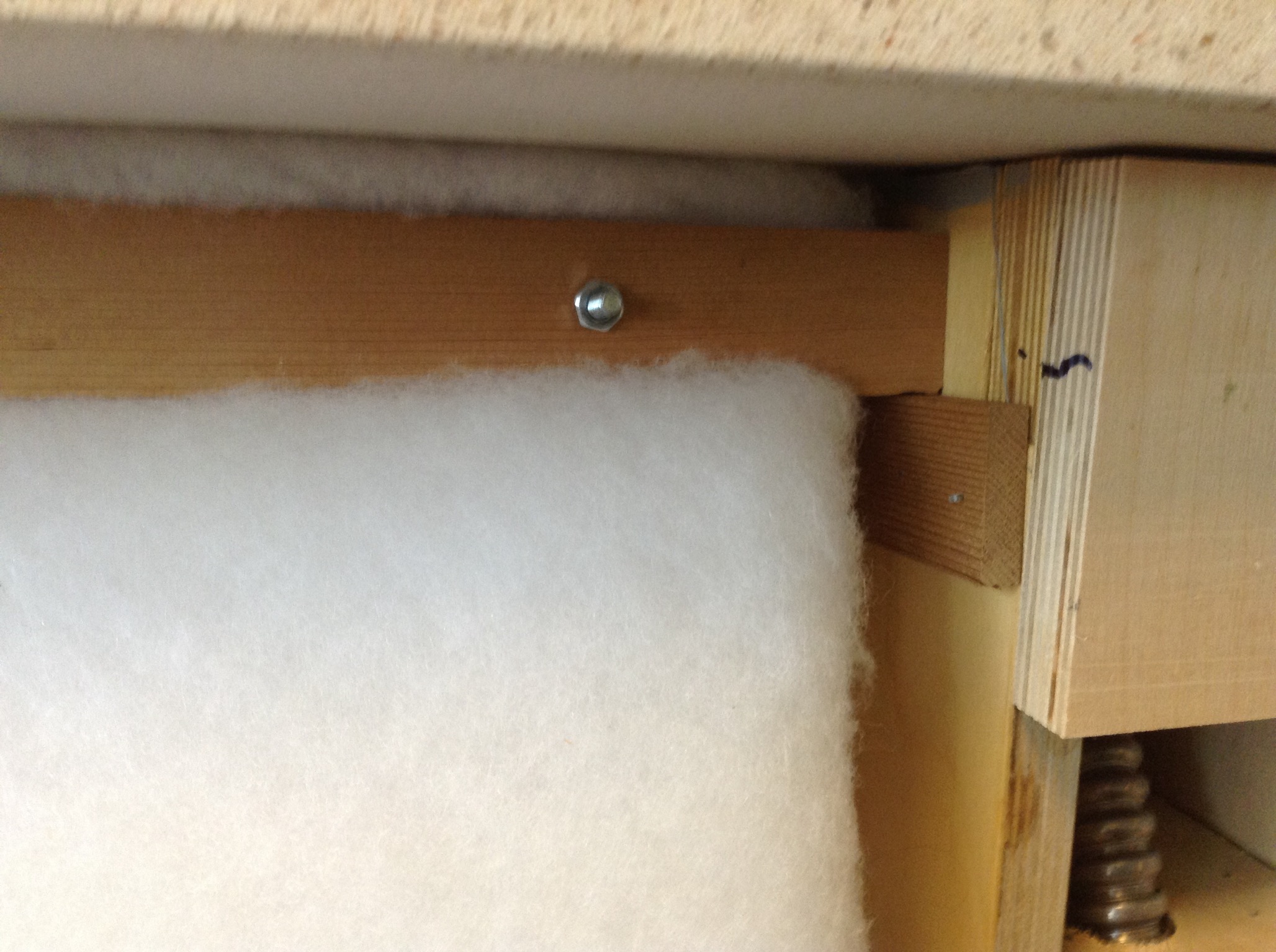
I removed the frieze and put it on top of the counter to show the curtain rod. Two quarter sawn 3/8" thick cedar sticks are used to sandwich and hold the batten in place. Four small bolts do the compression work.
+
Cleat detail. Hooray! I get to use the pneumatic brad gun for four whole brads. It really took a dozen brads. Porter Cable 5/8" x 18 AWG. I first tested on scrap to set the depth and made one install error and had to remove redo the cleat. FUN! Brads were used on the cabinet end to attach the filler strips also.
:
Ripping Sticks
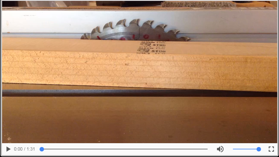
I'm using a 5' piece of a clear Hem-Fir 2x4 for the first batch of 1/4" thick measurement test sticks. Clear material is a bit safer to rip. When I visit Home Depot I often check the lumber racks for straight, clear, and quartersawn if possible. Look at that grain. Fast growing in wet environment. I set the fence "Open", where the distance to the blade teeth from the fence is greater at the back side of the saw blade than in the front. Just a little bit so the trapped piece will have less tendency to kick back. I stand to the left of the blade in case there is a rocket.
This is a non-imbedded mv4 movie. That's a hyperlinked snap shot of the Chrome player.
:
Balls
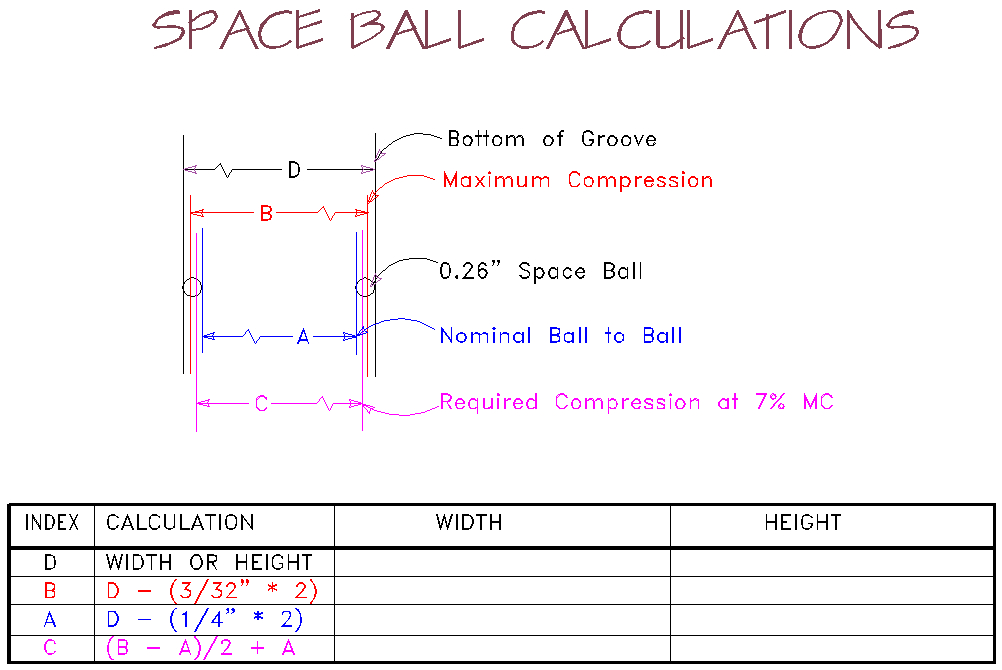
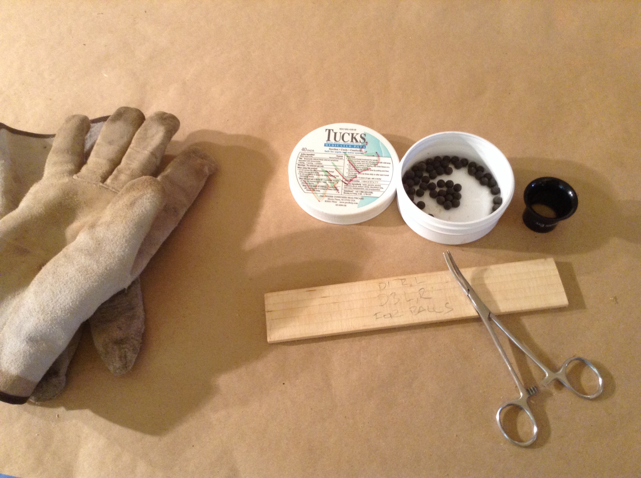
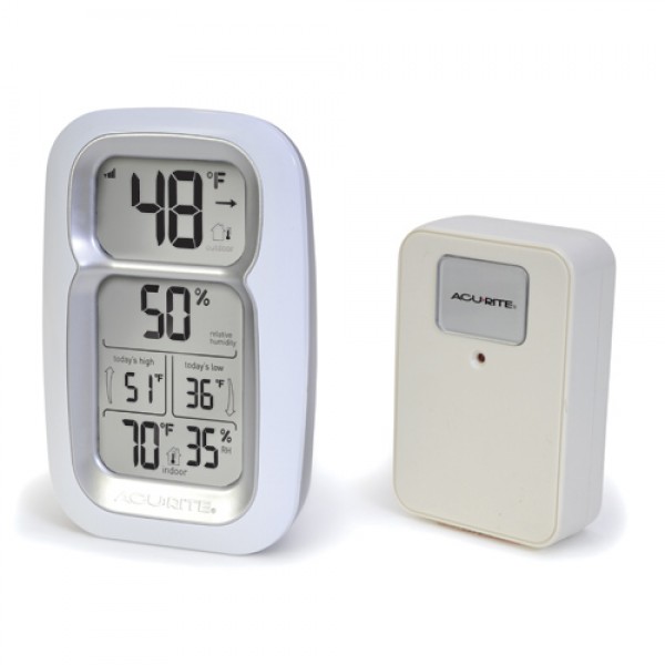
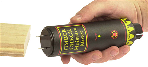
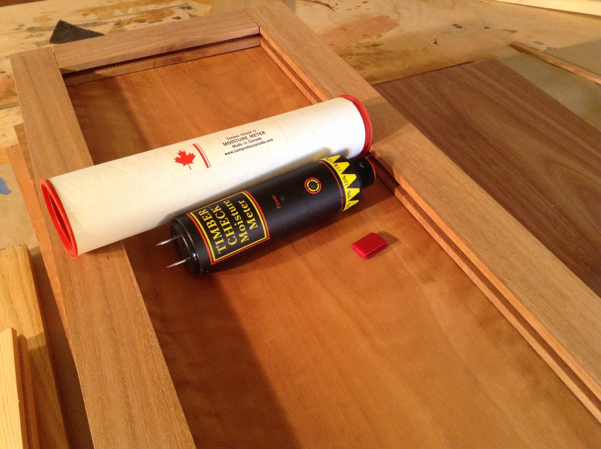
I have some balls... 0.26" Space Balls. They are resin, rubber-like, and made for floating panels. They are placed in the 1/4" grove of the stiles and rails where the tongue of the panel compresses them to allow for wood movement while keeping everything from splitting or rattling. It's spring and today when I woke up the relative humidity (RH) in the house was 49%. Yesterday it was 38%. I have tracked the RH in the house and it can be from 19% to 90%. Using the Timber Check Moisture Meter to measure the Lyptus shows a 7% moisture content (MC) during the day. The historic MC of the Lyptus I have here varies from 6% to 8% with the seasons.
Based on the MC the wood is midway in its movement cycle so the panels need to be cut at this time so the balls would be midway through their compression range. These Space Balls have a maximum compression point. I have squished them with pliers and in a panel groove with the vise to measure this. I find they compress to 3/32" from 8/32". The minimum compression would be 1/4". I have just enough balls to use two per edge. I'll use a drop of silicone caulk to hold them in place in the groove. The balls and the silicone don't bond but the caulk will hold them in place. Care must be used to keep the silicone off the surfaces that will be finished. This will simplify installation as the tenons won't be glued.
:
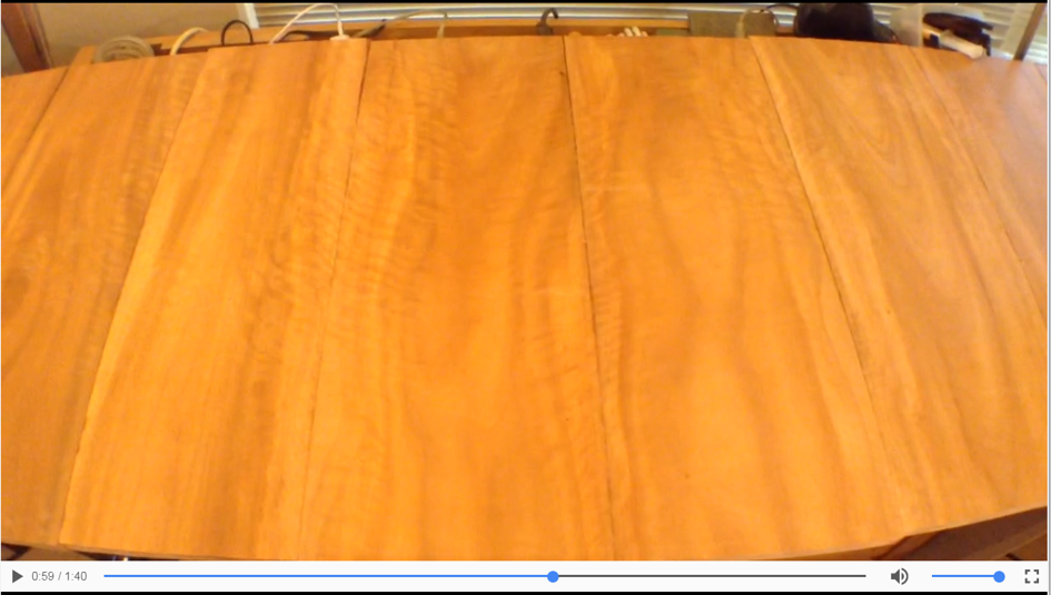
Lyptus Eight Panel Layout
This is the order and orientation of the eight Lyptus boards I'm preparing for the eight panel peninsula assembly.
Click on non-imbedded player image to run MP4
:
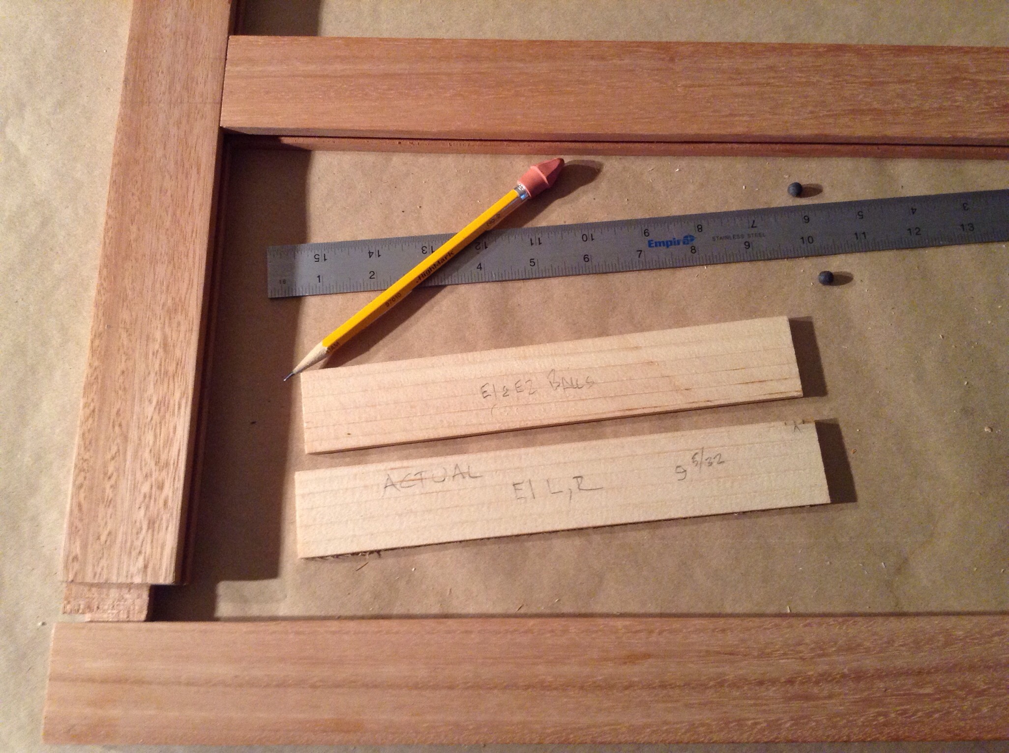
Test Sticks and Test Panels
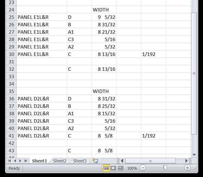
I make two measurement test sticks, Actual and Balls. I first sneak up on the final length of the Actual stick by cutting and testing. I test by placing the Actual stick in the grooves and see if all the joints get closed. I test for allowance of movement in the opening. There should be some. Also the stick shouldn't be loose. I measure the Actual stick and then use an excel sheet with the formula to determine the length of the Balls stick. I mark that and cut the Balls stick. Then it is tested with balls in the groove for a proper fit. I usually sneak up on this cut too.
Excel Sheet
++
This may appear to be a bit obsessive but I assure you it isn't. The sticks are cut with the Dubby on the left side of the saw blade. Next I must use the Balls stick as a gauge for setting up the rip fence on the right side of the saw blade. To test the setting I then rip a test panel out of scrap masonite and test for fit with four balls in the grooves. Always rip where the rip measurement is longer than the rip width to reduce the likely hood of kickback. When the test panel fits I then can cut the actual Lyptus panel. I think this is what they mean when they say measure twice and cut once.
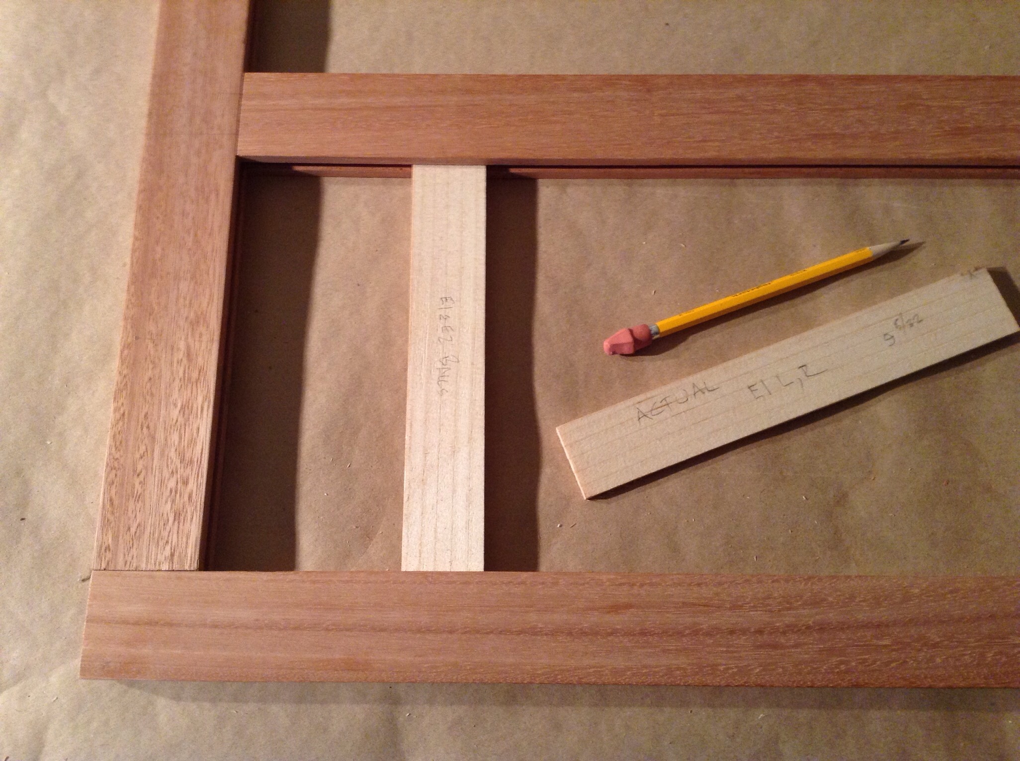
Preparing to test balls stick with balls for fit.
++
I test the Balls stick in each light (panel space) for a fit using a ball in each groove. I check that all the joints close properly with minimum pressure and that the stick is under pressure in the opening.
++
All the Balls Sticks sorted and lined up to determine test and final panel cut order.
++
After the Balls Stick's measurement has been transferred to the rip fence a 1/4" masonite panel is cut. The panel is tested with the balls in the groove.

++
When cutting the test panels cut from masonite extreme caution needs to be used. Risk on the saw involves a few separate issues. One of them being the answer to this question. If I did slip, trip, fall or slide into that saw blade what harm would I incur? Usually the degree of damage directly corresponds to the depth of the cut as well as the length. The risk from depth of cut is the first place you look when planning a cut on the table and try to minimize before you question the tried and true. Here this blade height is 1-3/8" above the top. Through the process of making measurements during the calibration I can say the arbour on this saw will put the blade out of alignment if I lower it. If I lowered it then not enough of the blade would be exposed to make the ripping fence parallel. Using a push stick to any effective level actually increases risk. It loads the potential and potential is risk. This saw will easily remove my hand.
++
This is the correct set up for this cut. Using a feather block which will work real well here as is not always the case for example; with natural edges. I can stand to the right of the fence making this a left hand cut. Not a problem even when I consider that I far have better control of the right so left handed cuts have a greater risk factor. I can measure how my right hand is so much better than the left in many tasks. The left is good at stabilizing and hey I can play piano with them and I love the left basso so I do have some control. If I orient my hips parallel to the front rail then if I fall I will fall forward so it won't be towards the blade. A significant risk is eliminated with proper body placement for every cut that offsets the 1-3/8" blade height risk factor that could result in limb damage or loss. Also It feels good doing this cut because the body isn't under any twisting torque. The motion requires little force so the pectoralis aren't involved much with masonite. The deltoids, bicep, and the forearms are the primary muscle groups under contraction stress.
++
The balls are tucked away neatly between tests. I don't want to loose my balls.
:
Keeping the Work Environment Neat.

:
Ripping With the Ripping Fence
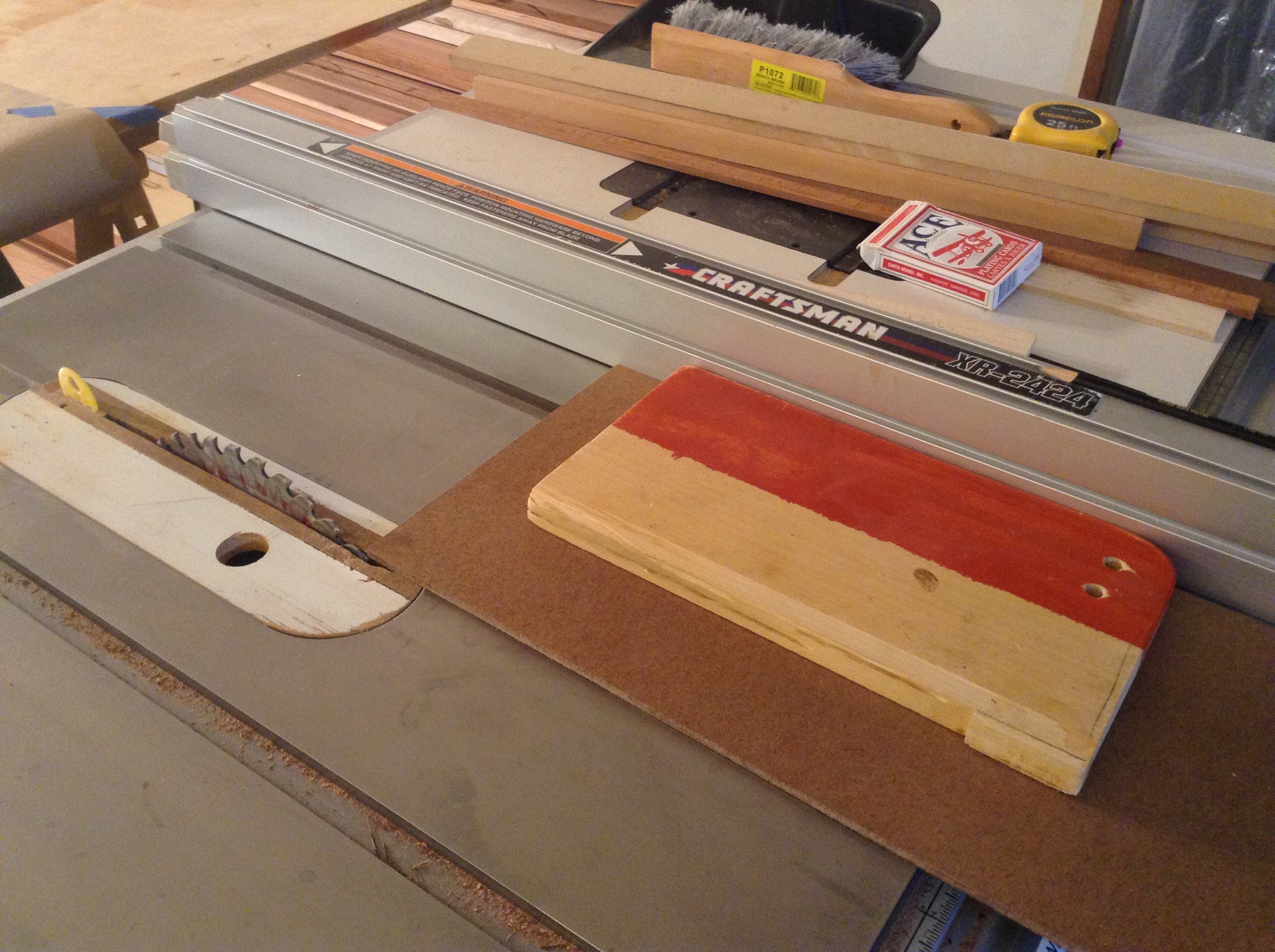
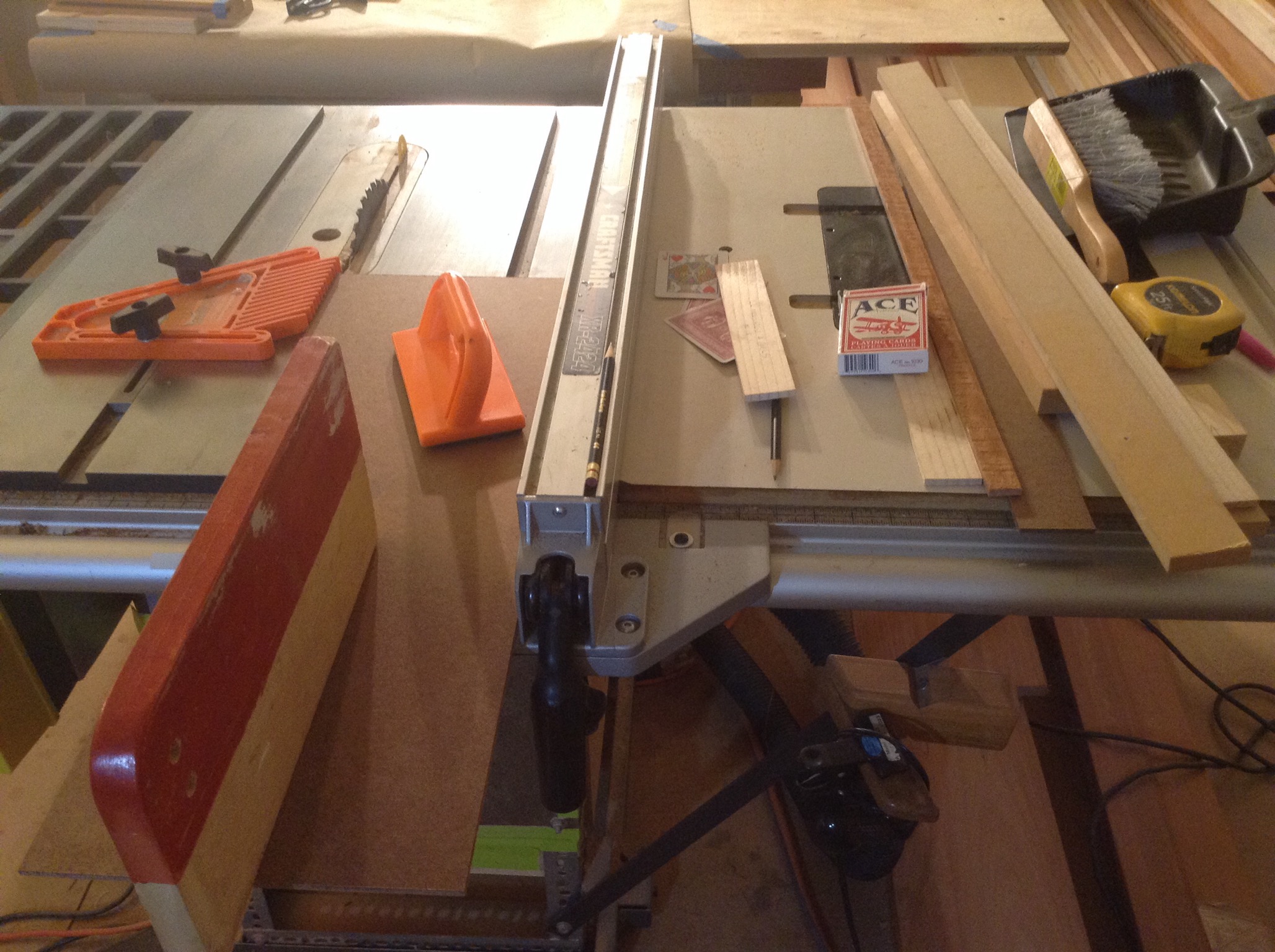
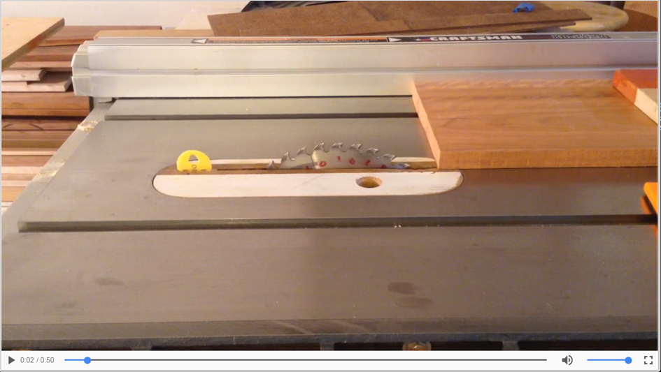
Using the ripping fence safely requires a few extra steps to minimize risk. Keeping the blade's projection above the piece minimized reduces accident risk and extent of damage. This may reduce the quality of the cut but for this cut its acceptable. The fence should be set open to reduce the likely hood of kick back. I use a playing card for this. On the front side of the blade I measure from the outside face of a tooth to the fence. On the back side of the blade I measure from the face of a tooth to the fence plus one card. This creates the open setting without sacrificing the quality of the cut significantly. This open setting just widens the kerf. I can still get a rocket so the position of my body in front of the left side of the blade helps keep me out of the trajectory of most projectiles and using push blocks keeps me outside the blade's dome of danger. This is panel C2 (see drawing at top of page) being ripped to final dimension.
Click on non-imbedded player image to run MP4
:
Crosscutting to Height
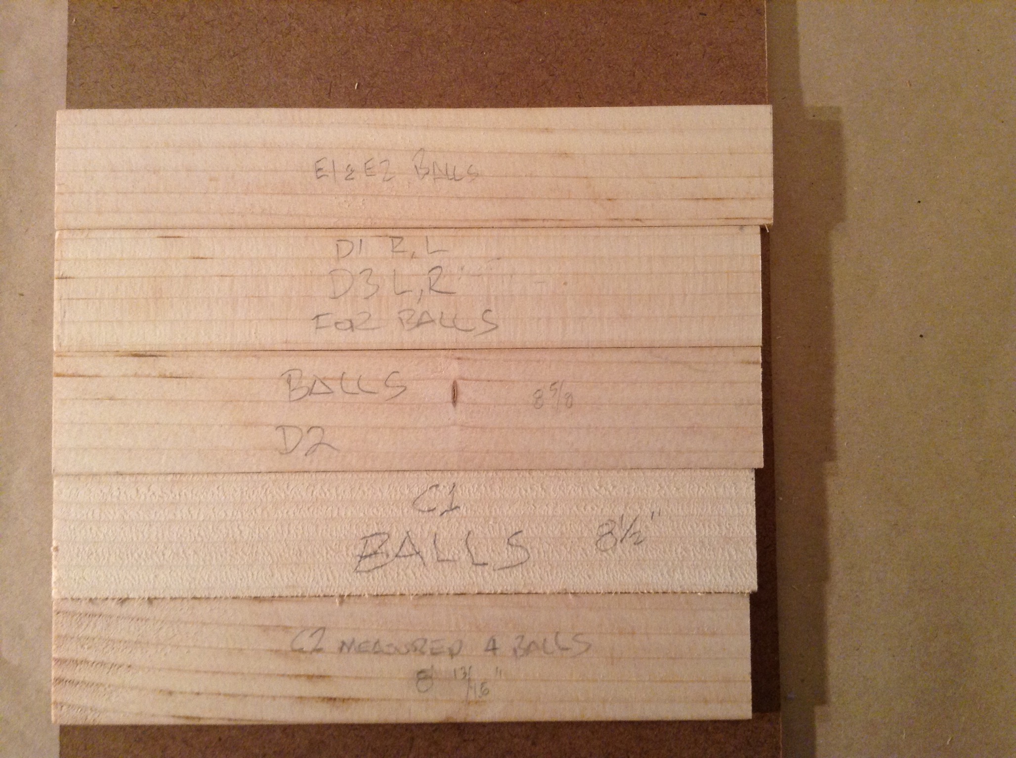
An Actual stick and a Balls stick were cut and tested for the height of the panels. They all can use the same height panels. The two-light E panels are a very tight fit. I'll need to sand off about 1/64 on each end grain side to shorten by 1/32 to allow for any expansion on this axis.
After setting up the Dubby for the exact measurement during the cutting of the Balls stick I realized that both ends of the boards needed a 90 degree crosscut. So I set up the second Dubby and performed test cut calibrations for 90 degrees then cut the first crosscut for all the panels. I cut one or two blade widths off the bottom on most but a few on top. The end chosen was due to the grain pattern evaluation process performed always before a cut.
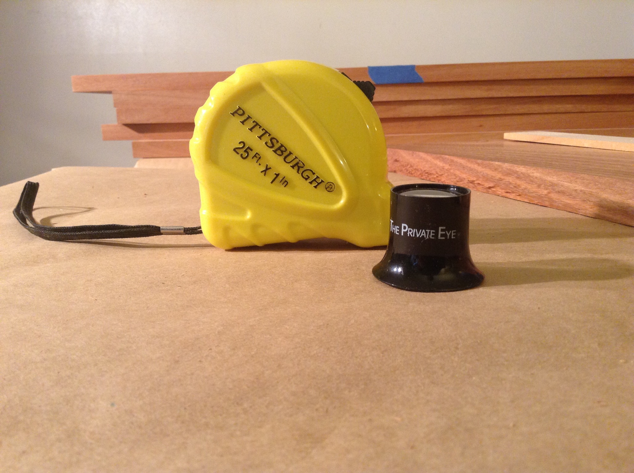
Panel EL is the longest as there is an open knot on the top edge that needs cut off when cutting to final length. I removed a blade width off the second crosscut side and measured the diagonals. Both were 31-1/2". I'm using the 1/32" rule and a shot-glass loupe. I can repeat the measurements. Perfectly square to within 1/128" as no interpolation is required when taking the measurements. For diagonal measurements I always use my trusted tape measure. Trusted means It's measurements equal the shop's most accurate finest steel ruler when using the catch in push or pull mode. My trusted rulers are the 16" square or the 18" flat. The center of the tape measure's catch is hooked over the center of a corner (The catch is made for this) and the tape is drawn to the opposite corner and a measurement made with the appropriate measure scale using the loupe. This operation is then done on the opposite diagonal and the numbers compared.
This tape when using he hook over an edge is 1/64" short.
++
After the last cut for each panel was completed the diagonals were measured and recorded. The notes are forward looking at the next step, the milling operation, with the router and the tapering jig. The variances ranged from zero to 1/32" with an average of 1/53". The variations can be attributed to the rip cuts not being parallel among other things. A hundredth of an inch here and a hundredth of an inch there and you have the one fiftieth.
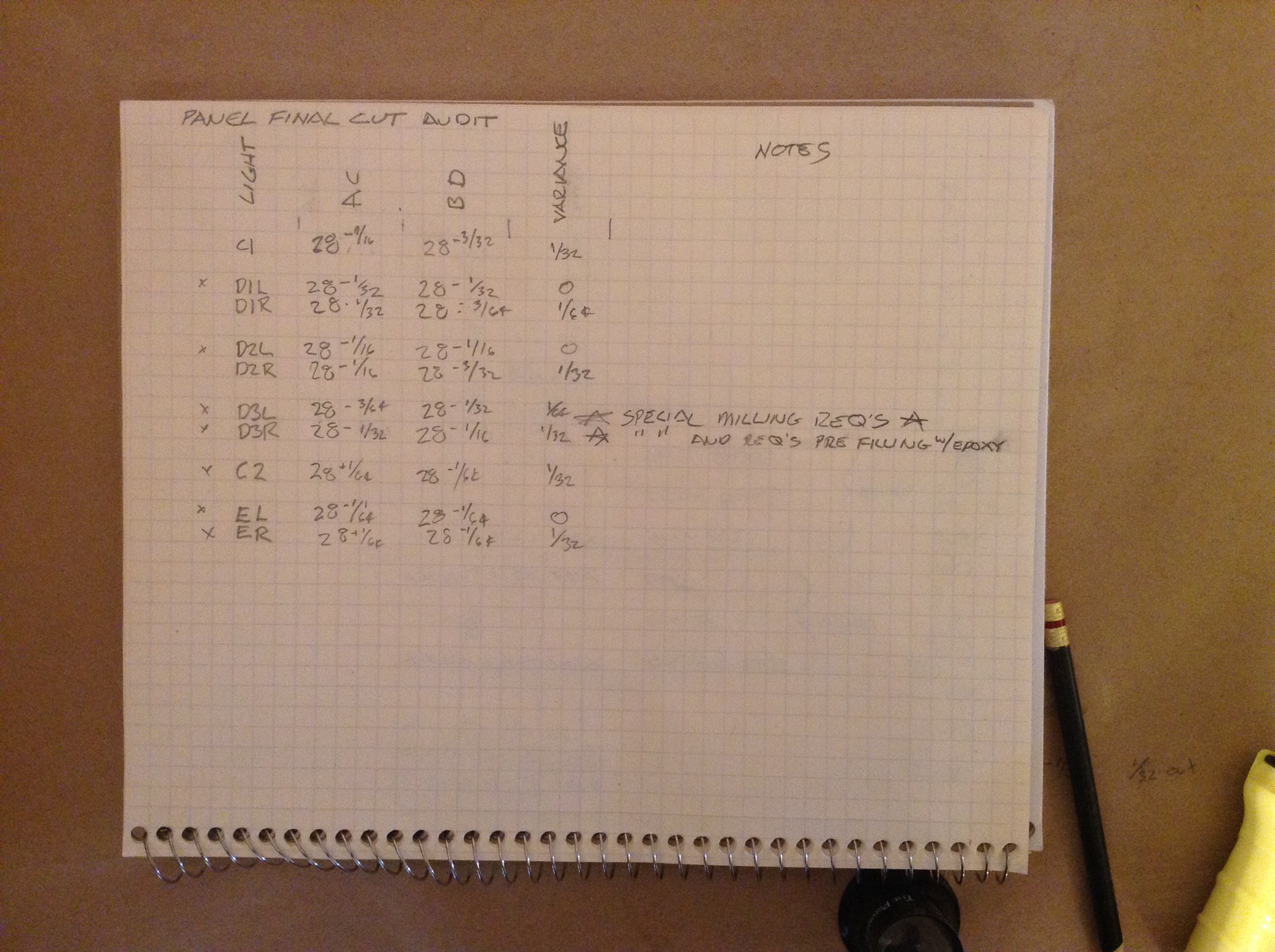
All Cut. The panels equal 1.26 cu. ft. of heavy lyptus. These panels are beautiful.
:
:
Adhesive Selection
I generally use Titebond.
For these doors I'll need to purchase new so I can evaluate their specifications to make a selection.
The initial choice was Titebond III Ultimate Wood Glue because of it's working time when compared to I or II is good. Their website says 8-10 minutes. Note the spread requirement of 6 mills. A mill is a thousandth of an inch. A magazine cover is 0.005". Guess what my feeler gauge will be?
Application Temperature
Above 47°F.
Open Assembly Time
8-10 minutes (70°F./50%RH)
Total Assembly Time
20-25minutes (70°F./50%RH)
Approximately 6 mils or 250 square feet per gallon
Enough to bring joints tightly together (generally, 100-150 psi for softwoods, 125-175 psi for medium woods and 175-250 psi for hardwoods)
Plastic bottles for fine applications; glue may also be spread with a roller spreader or brush.
Damp cloth while glue is wet. Scrape off and sand dried excess.
The next choice was Titebond II Extend Wood Glue. Its open assembly time is 15 minutes. Its spread is also 6 mills.
Application Temperature
Above 60°F.
15 minutes (70°F./50% RH)
20-25 minutes (70°F./50%RH)
Approximately 6 mils or 250 square feet per gallon
Enough to bring joints tightly together (generally, 30-80 psi for HPL, 100-150 psi for softwoods, 125-175 psi for medium woods and 175-250 psi for hardwoods)
Easily spread with a roller spreader or brush or may be transferred to plastic bottles for finer gluing applications.
Damp cloth while glue is wet. Scrape off and sand dried excess.
Both of these adhesives are strong and the difference, 3844 lbs/sq. in. and 4000 lbs/sq. in. for II and IIE respectively, is small and not critical for my purpose. I am attracted to the longer open time of Titebond II Extend because I have a PTSD emotional reaction to glue-up that is somewhere between panic and terror. I have used Titebond II and IIE before and the longer open time is still just not enough to quell the panic. The door requires the strength properties of this type of glue so I have few choices. I am going to over come this this time! Yah-shure. I have considered gluing up two of the four joints then after drying the second set of two joints. I am concerned that the torque stress formation could be uneven and counter to the final squareness. I think there probably an advantage to massaging all four joints square at one time with small changes in clamp pressure. The only thing I know is "The Diagonals Rule" or TDR or Time Domain Reflection. TDR is when you un-clamp a dried glue-up door and measure it to find it is out of square. Whenever I reflect on time I can identify errors. This makes me a bit negative. Whenever I plan for the future I think positive. The math on all that actually works too. More importantly, Time moves slower for me in Edmonds than me in Denver.
So... Titebond II Extend Wood Glue it is.
:
Bit Inventory
Ready. Check.
:
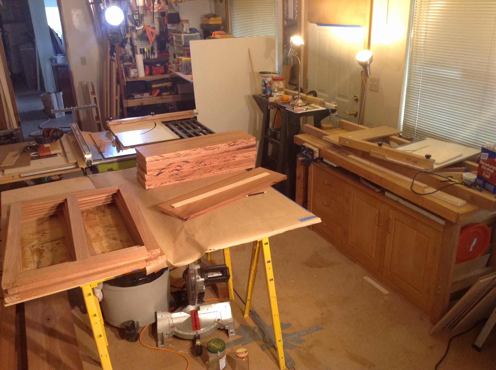
Not Enough
I do not have enough of the quartersawn Lyptus in the same thickness to build the doors. I must stop and begin a cutting and planing effort of both Lyptus and soft wood to build the doors. I need one stile and one rail plus more than enough softwood stock to build a door. I need 13/16+1/64 thickness. I have two Lyptus boards that are 13/16+2/16. I need to plane off 1/64 and absolutely no more plus minimize snipe. Actually 1/128th off each side because the groove is centered. Not an easy task. Fun challenge though. Reorganize the room for this not so much... because it requires lifting heavy... the planer and setting up level on and off ramps at least as long as the longest material. A bad setup can snip 9" off each end. With a good setup getting the loss less than 6" is possible. Sometimes none. I use a sacrificial compression carrier shoe where I alternate longer softwood with shorter Lyptus trying to sacrifice the softwood.
You can see there is a missing stile and rail for the right door. The material above and to the right of the right door is the material that could be planed. To the left and top left are the frames and panel blanks for the peninsula
:
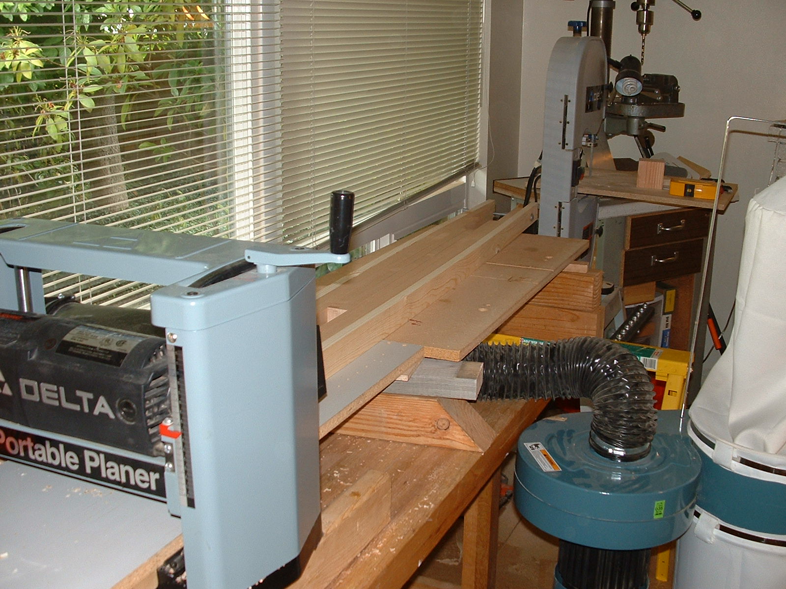
Delta 12" Portable Planer
Model 22-540
Setup, clean, and inspect. The two bushings are 1/2" long and should be replaced at 1/4". I'm going to get a replacement for the missing machine screw for the end shroud so I'm ordering a set of bushings too. The blades are all used one pair in good pit free shape. I'm considering another pair later if needed. The best cost is Home Depot of Lowe's that I can pick up anytime. Knives 22-547.
:
:
\';-} the squiggly smiling one eye'd winker topped with a tilted balmoral hat.
: