Converting a 2' T12 Fluorescent Lamp to LED
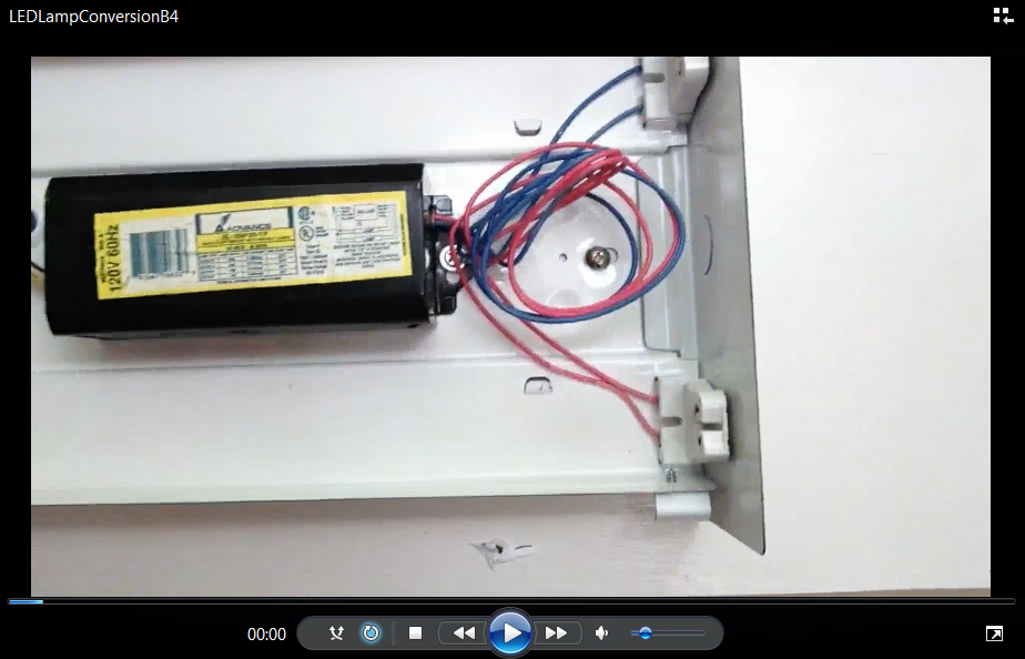
Click this picture to view a m4v movie of the wiring detail before conversion.
:
This is a screenshot of a 230 volt AC LED wiring diagram. 230VAC is used in commercial buildings. I have 120VAC in my home. The AC connection is the same for both voltages just two points for each bulb with it's array of LED's.
:
The Problem
Read this PDF
Schematic_LED_Conversion-lifebulb-lbp8f1241b-installation.pdf
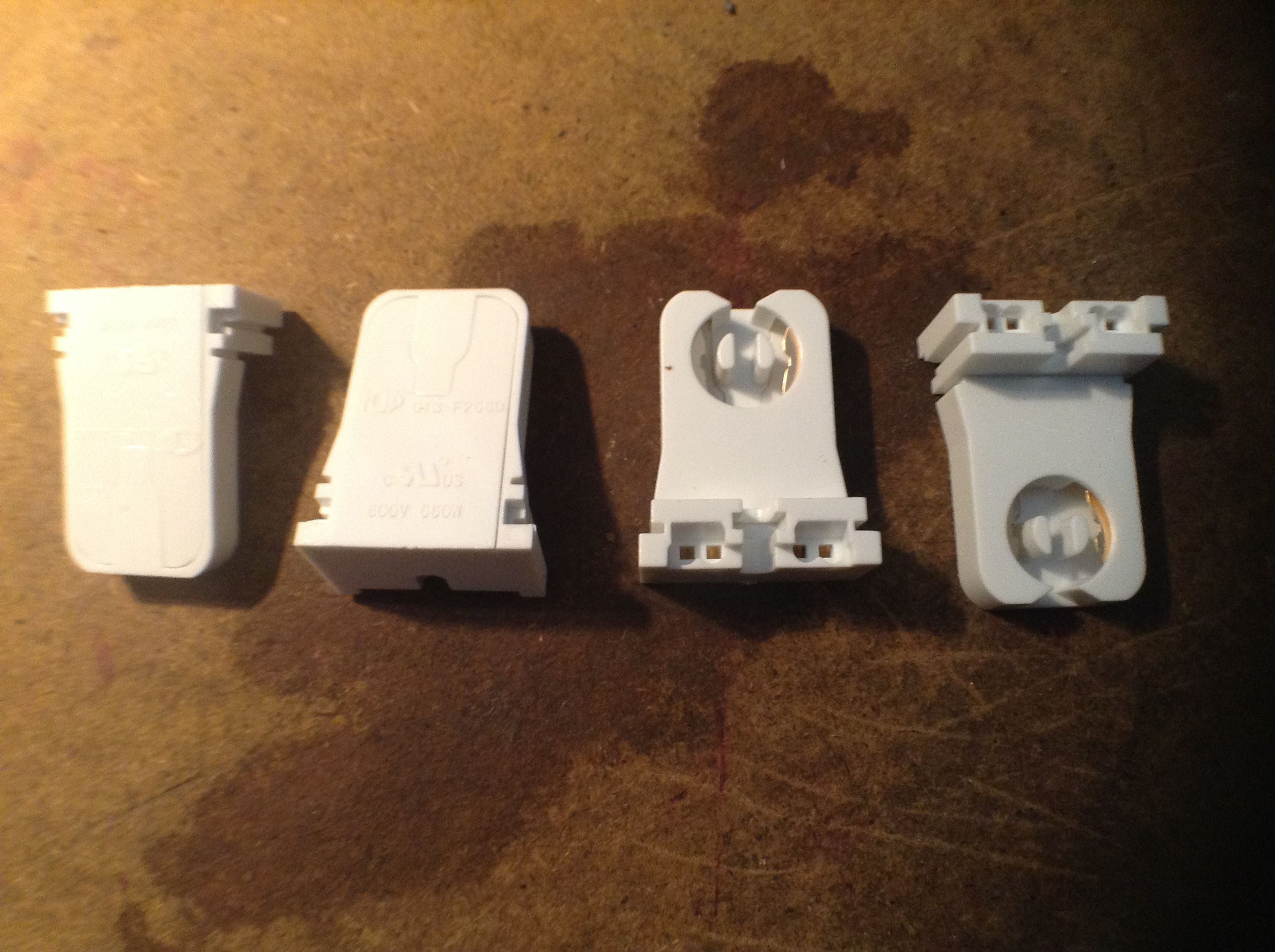
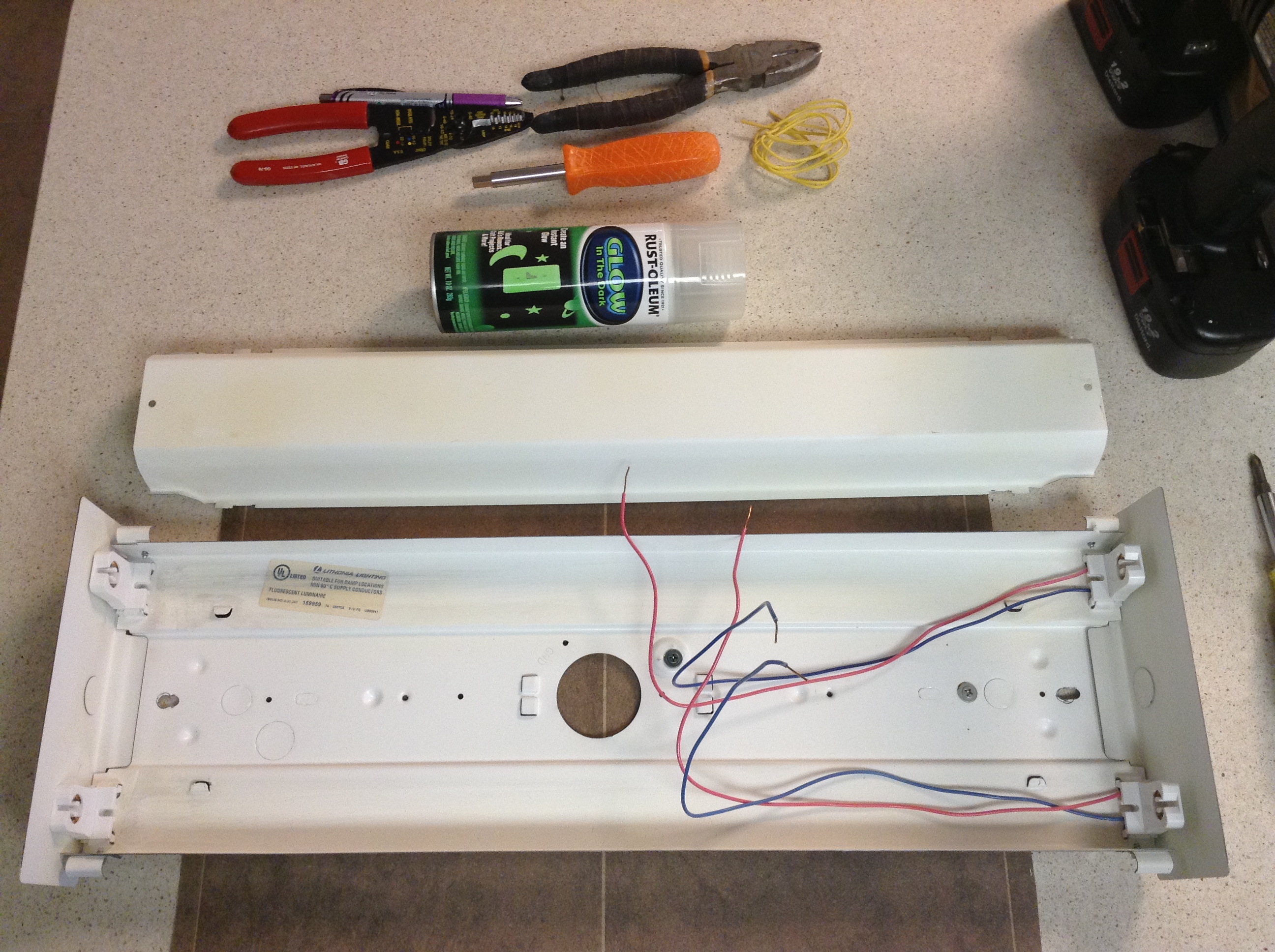
If you have an instant ballast the T8/T12 sockets are the incorrect type. They are shunted. LED bulbs require non-shunted sockets. I have a lamp that has instant start. I checked around on line and I can't find the same size 24" x 9". I can find 24" x 11+1/2", too wide, for about $100.00. So I'm going to get four of the correct sockets from Amazon for $5.79 and replace all the old ones with the new ones. The connections were older and full replacement is simple.
:
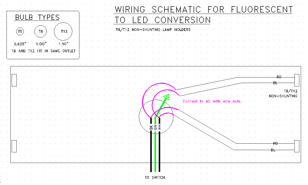
Schematic for Lamp Wiring
:
Pending parts order
So here they are five days after order from Amazon. Look at these carefully near their base. The first set of grooves midway up the base are the common grooves used for installation. Some lamps however use the next set up on top of the base where the holder section mates with the base. These are used in some lamps. Be observant when removing the old or better yet replace them one at a time.
:
This is how I knew I could convert the lamp. There are four of these nuts that hold the end plate in place. These are 1/4" screws and I use my screwdriver handle without and tip in it. Pay attention to the placement on the lamp holders as there are two sets of grooves that can be used. I photograph everything before disassembly.

:
This is a detail of the tool used and the result. I reversed the screwdriver and tapped on all four lamp holders until they backed out and were free.
:
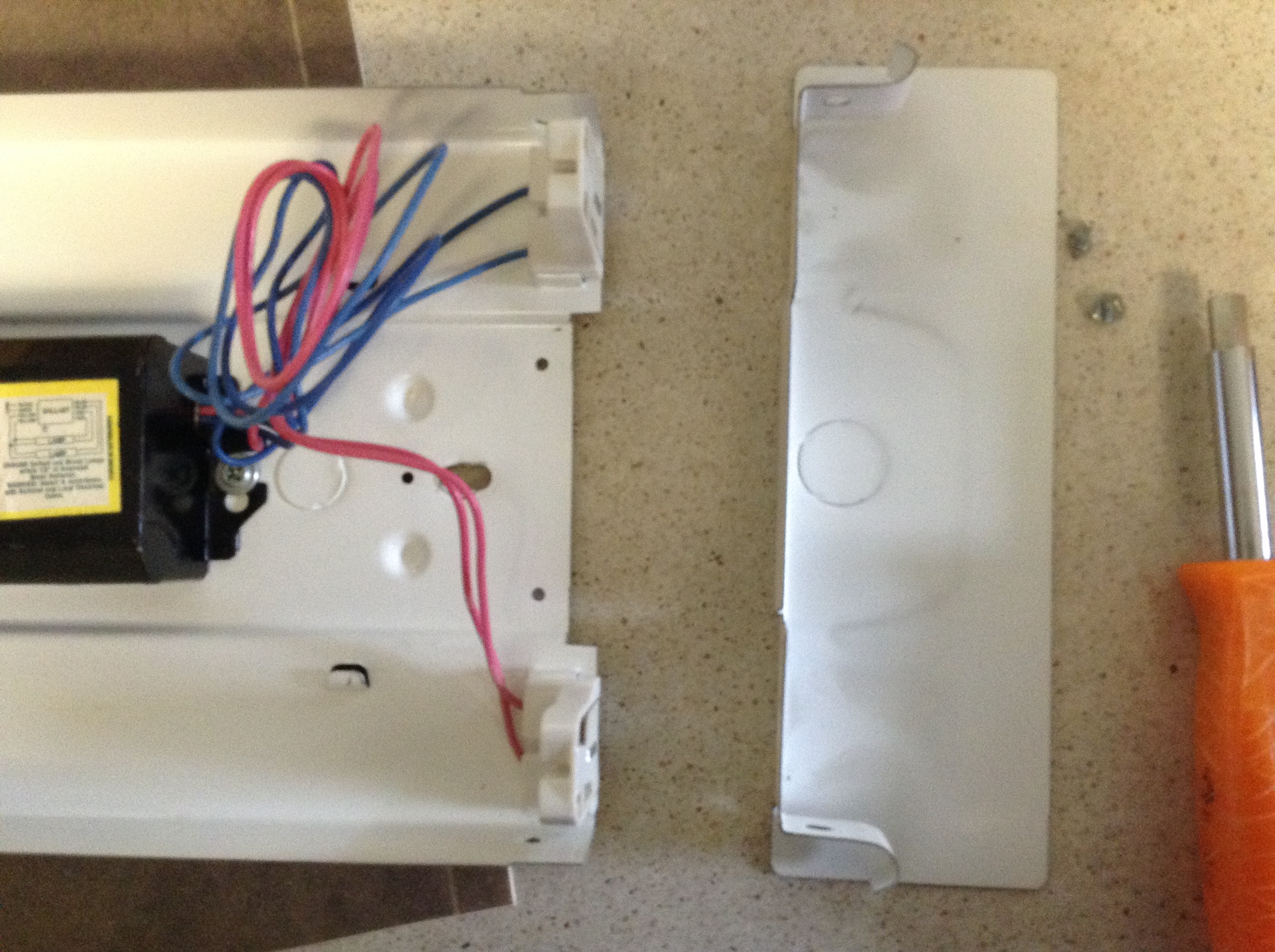
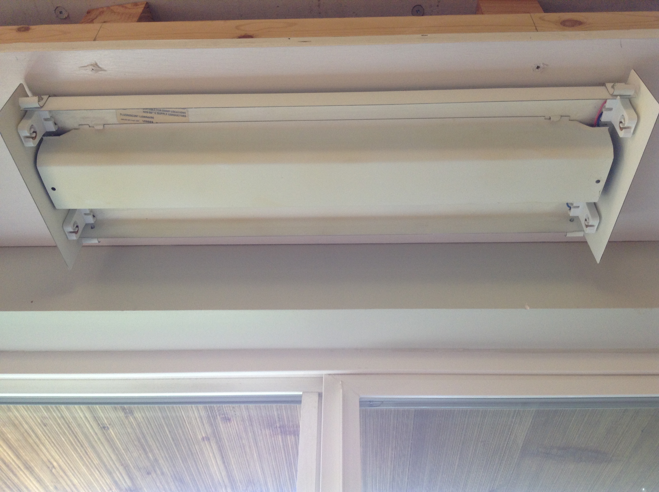
The ballast is shown removed and the new lamp holders installed for test fit. The old bulb was used to check if this was correct. I had to pound down tabs on the fixture to tighten up one of the lamp holders that was too loose.

:
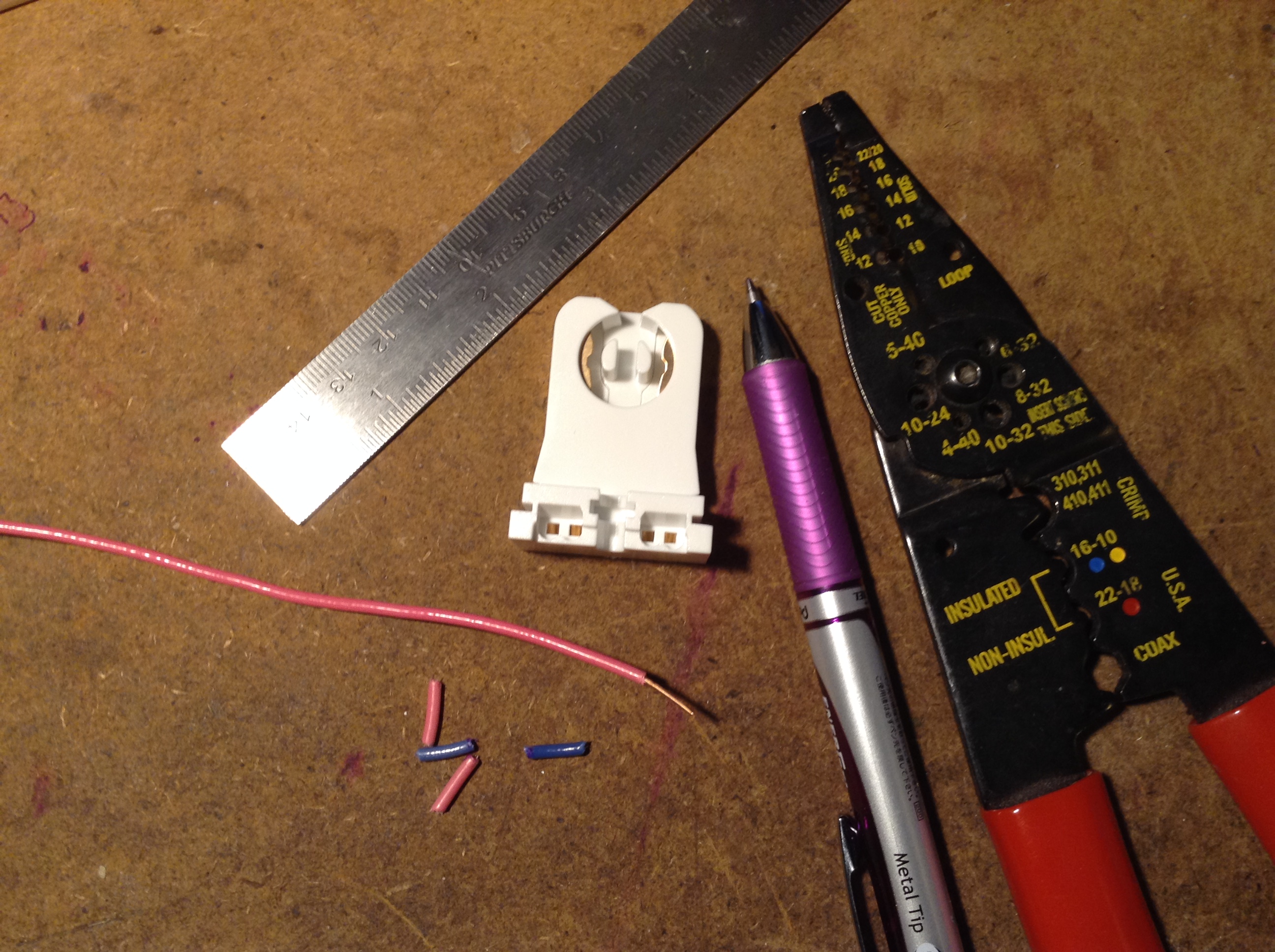
I scavenged wires from the old ballast because I knew they had to be the correct rating and gauge. These wires are solid 18 AWG (American Wire Gauge). For this type of lamp holder there needs to be 3/8" of exposed wire. See PDF Table. I measured, marked and stripped the sheath off one end of each wire. This final color code is technically incorrect. It should be black/white not red/blue. I'm OK with this exception in this narrow variance as there is total visual continuity at one work location. If the wire is multi-stranded the ends need to be tinned using solder and an iron or dipped in a hot pot.
;
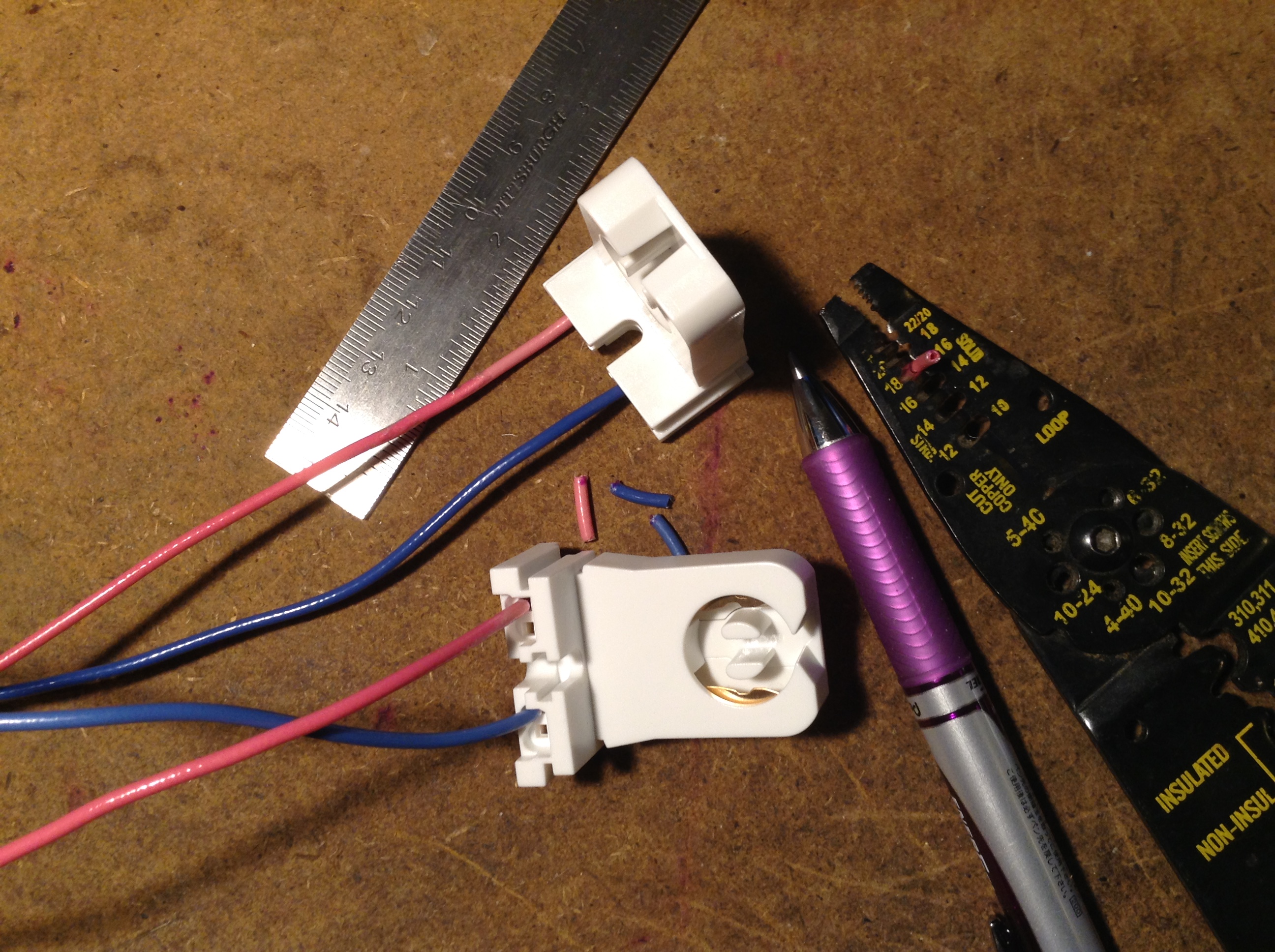
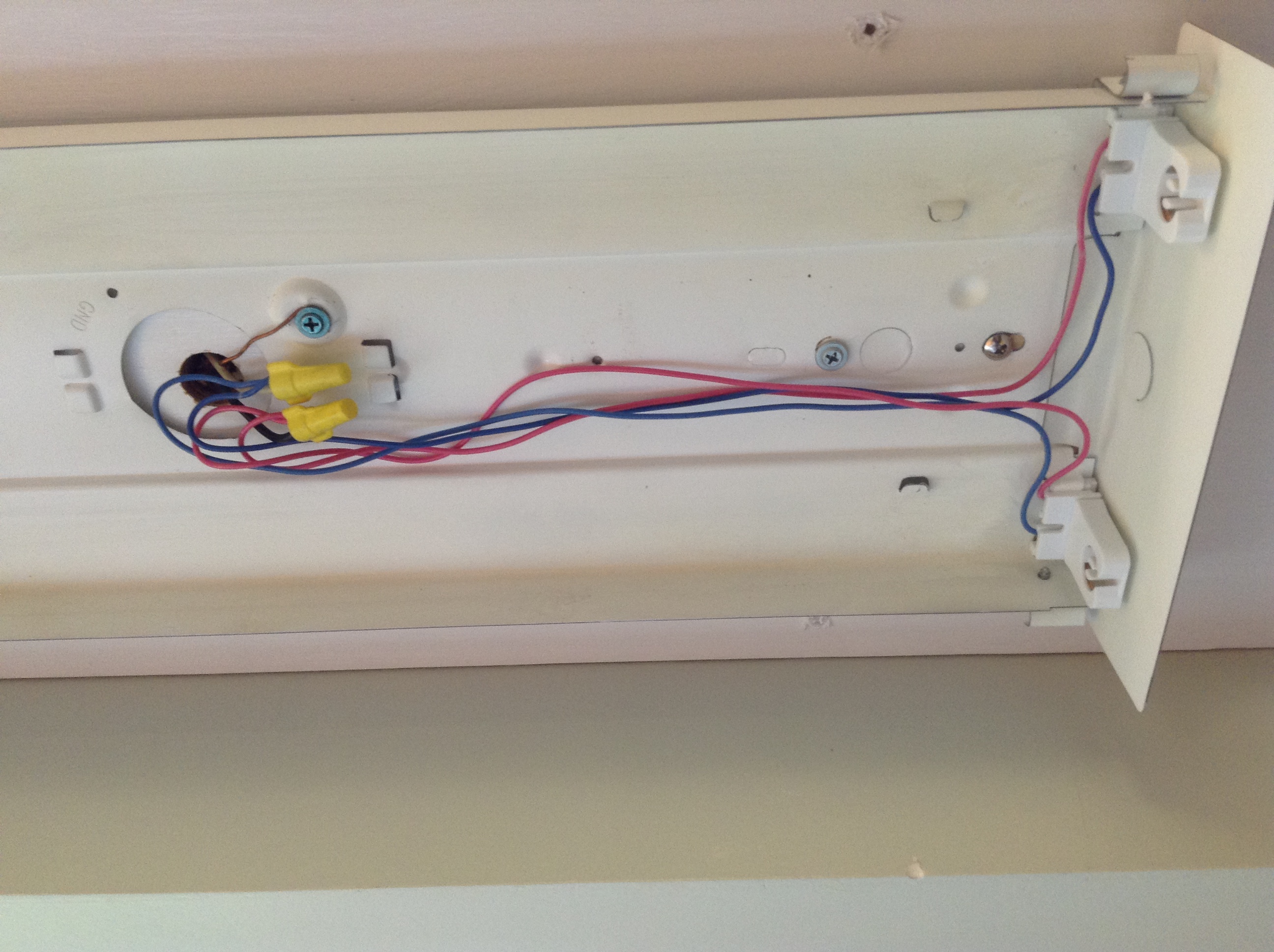
Here are the lamp holders connected. Just push the wire into the hole all the way. The red wire here is Line and the blue Neutral. No copper should show. Say, no shiners. Don't forget to strip the other ends after the lamp holders are done and while the lamp is down on the work table. Don't wire out the opposite lamp holders at all. I used my volt/ohm meter to test each and every lamp holder and connected lead for correct operation; isolation (open) and continuity (short). Passed as good as a UL stamp of approval. You can see which stripping slot I used. Love that tool because it does so much so very well.
:
This is the bulb I ordered.
:
This is the spec. sheet for the bulb.
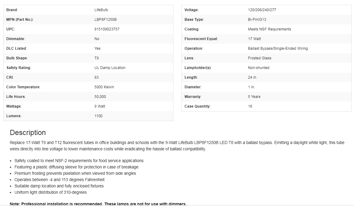
Leviton Data Table for Wire Preparation Specifications.
:
Sprayed all the showing internal surfaces of the lamp with Glow in the Dark paint. The center flat will be behind the wire and ballast cover so don't paint it and the ground screw. When I turn the lights off in the kitchen at night the lamp will glow green for about 15 minutes or so. Real cool.
:
Screwed up and wired. You can see I had to use a landing screw hole on the fixture instead of the GND hole due to the wire length available. Yes I could of extended the ground but I figure I get the same ground potential (after scraping a bit of paint off) and eliminate another connector in the circuit. With the yellow wire nuts first screw-connect the two 18 AWG conductors as this will twist up these two fine gauge wires nicely. Then unscrew them, add the conductor from the switch, and screw all together again. Red is black and blue is white.
:
With the wire cover in place. Where are those bulbs?
:
The bulbs arrived.
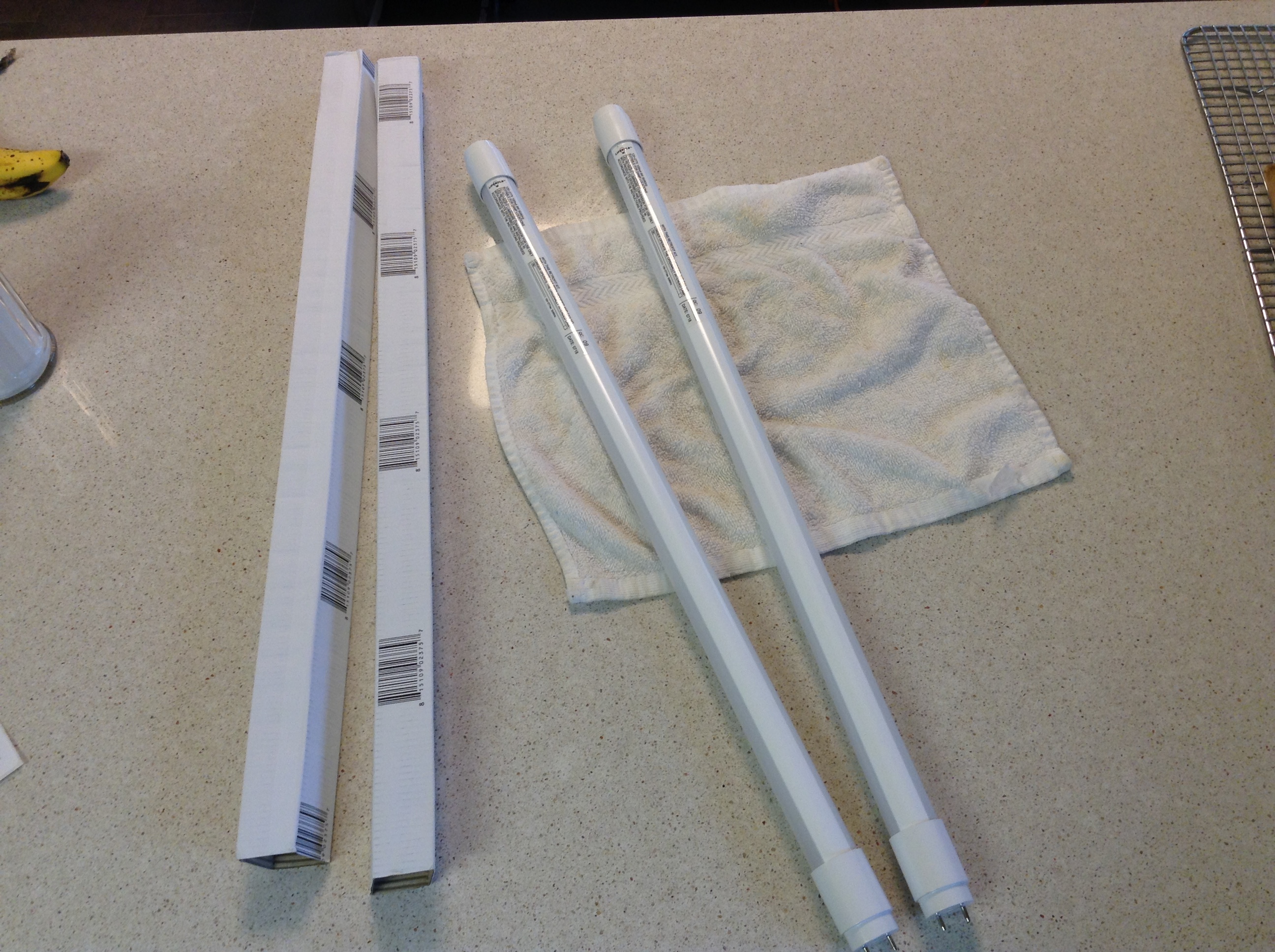
:
This answers my question about the polarity, are the bulbs labeled, and yes they are. L & N are shown the back side of the hot end.
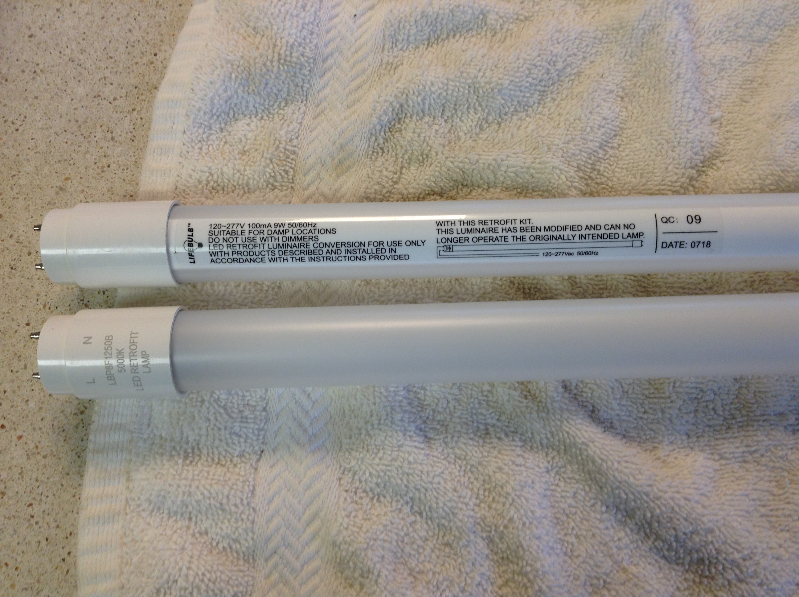
:
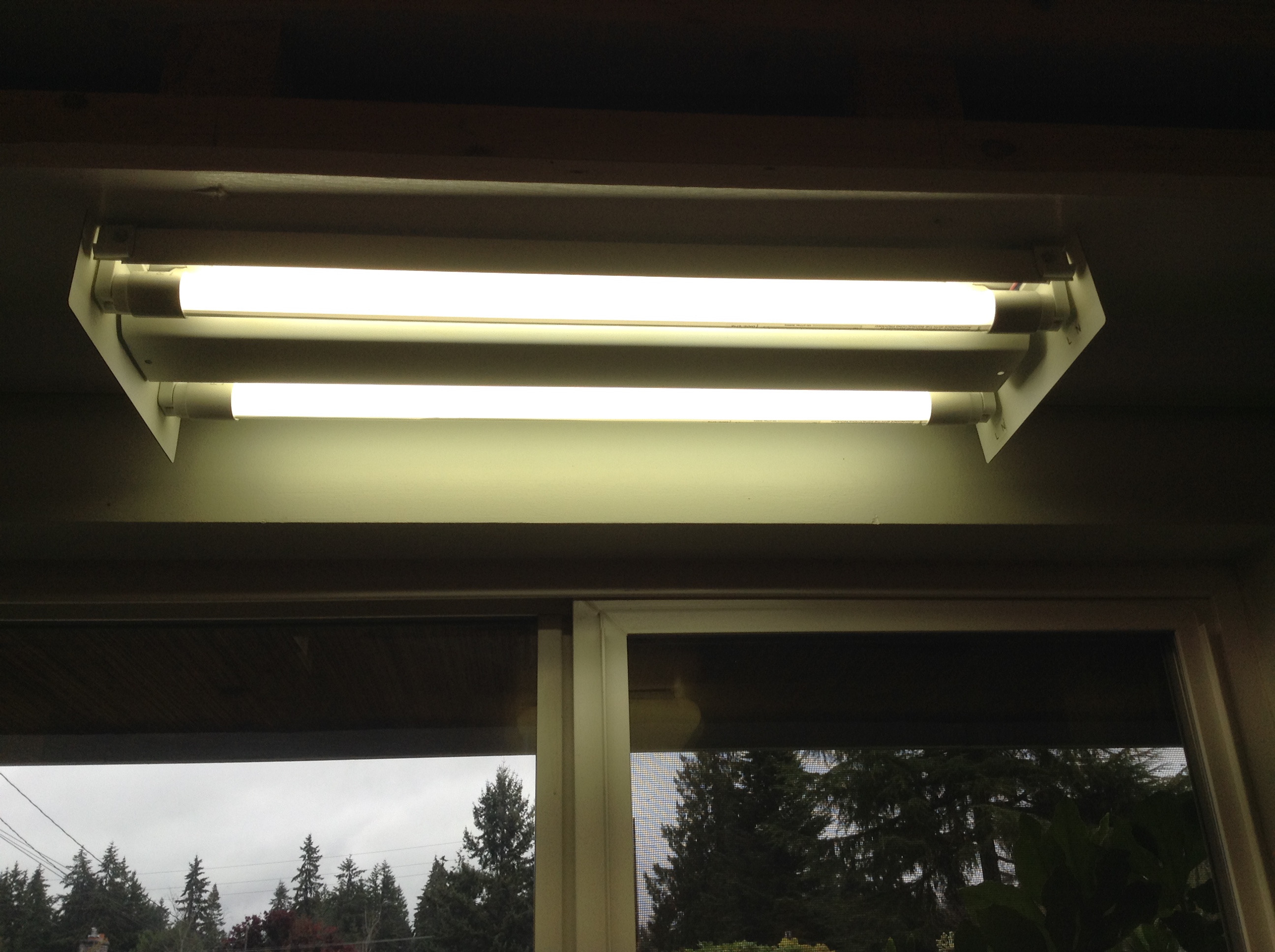
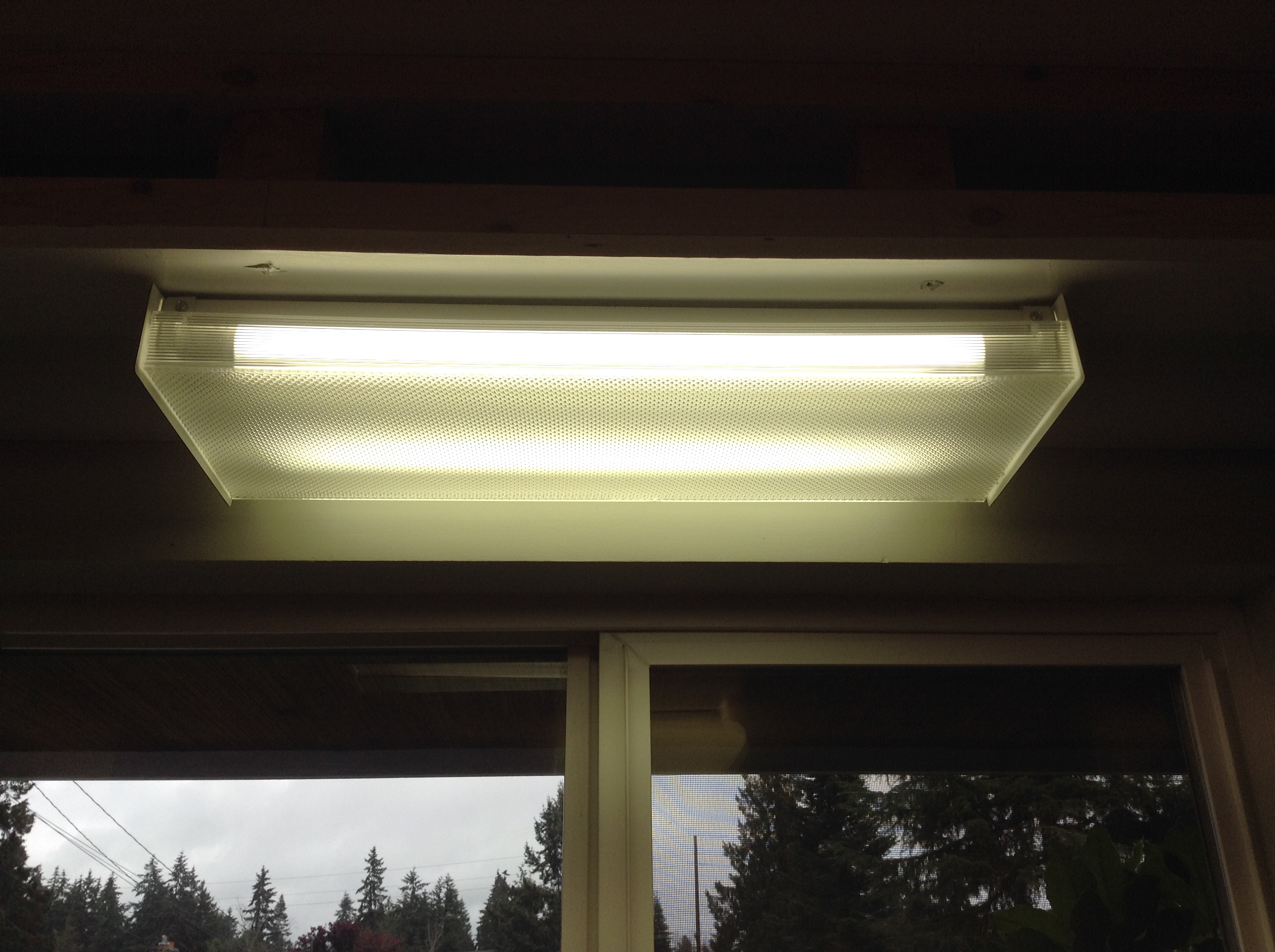
The bulbs work well. I installed on a hot circuit. No problem. If you open the picture and zoom in with the Ctrl and mouse scroll you can see I labeled L/N near the hot end lamp holders for the next guy... I'm the next guy.
:
With the lamp cover on the LED conversion of 2' lamp over sink is done. I needed to see the bulb's color and compare to the fluorescent. These bulbs are 5000k and so a fuller spectrum than the fluorescents so they appear whiter. I can see more detail so they are better for task lighting. If I want mood lighting I can use the warmer under cabinet LEDs or the under range hood lights. I'll use 5000K's for the 4' fixture I will be working on next. It's gray outside today, mmmm, I really like that because it says cozy day inside.
:
This is what the Glow in the Dark paint does when the lights go out in the night. Put the paint everywhere you can and apply a second coat too. What the camera doesn't show is the sink is fully lit. It can be seen from the studio. The green glow slowly fades out.

:
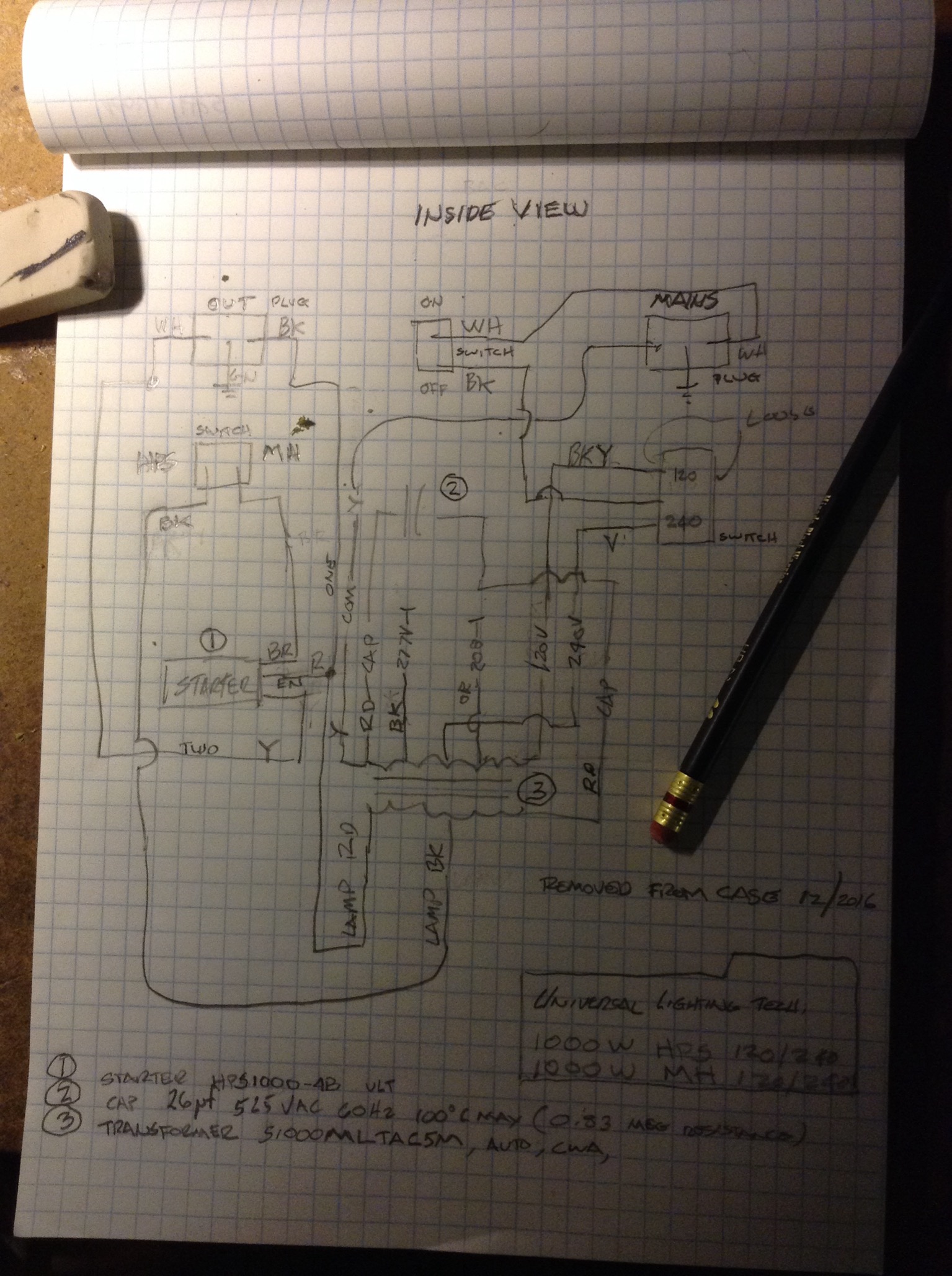
Other Lamp work
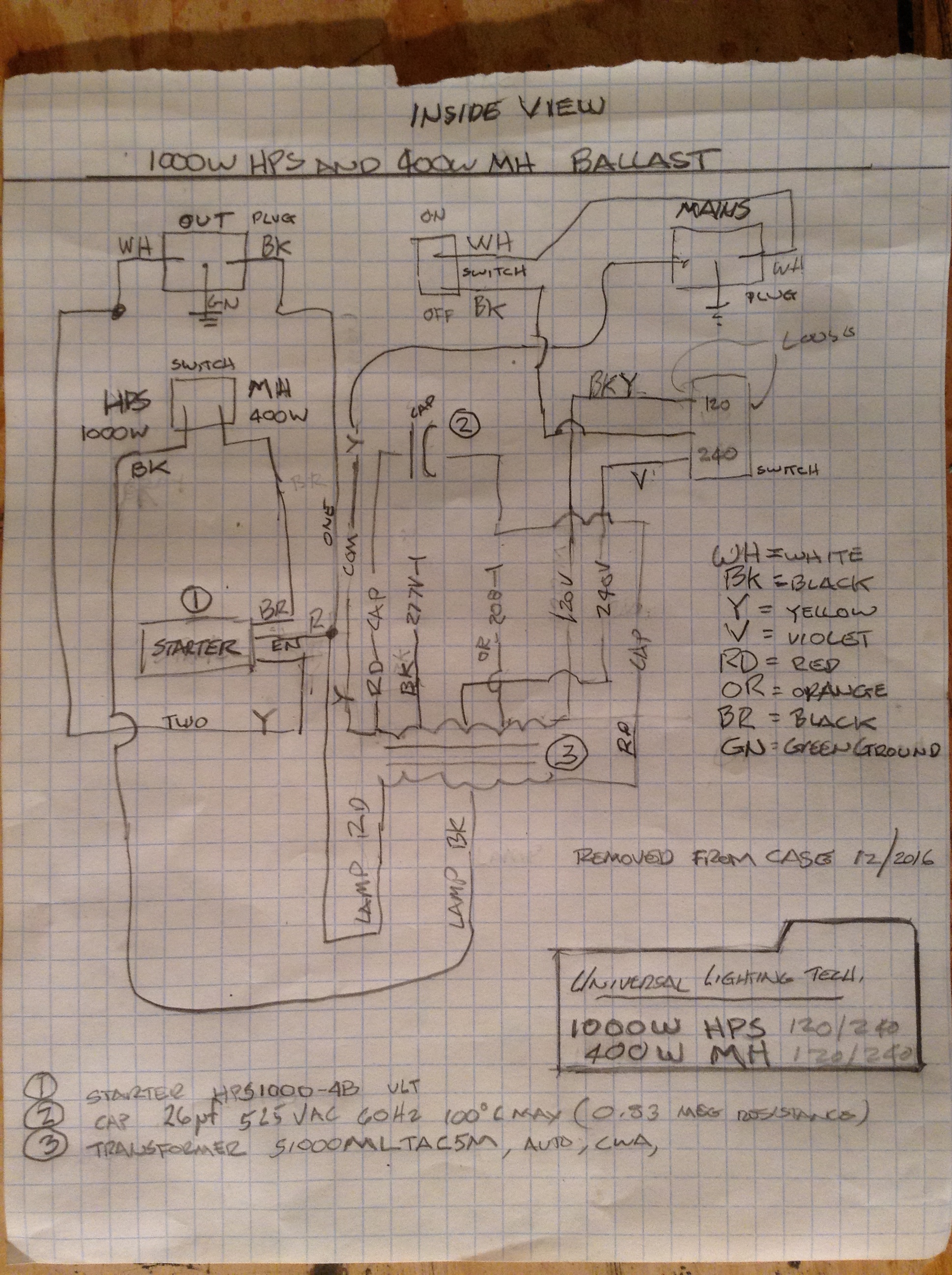
1000W HPS SCHMATIC
:
10000W HPS and 400W MH