


2-1/8" Deep
2-1/8" Deep
1-1/2" Deep
2-1/8" Deep
1-1/2" Deep
3-1/2" Deep
2-1/8" Deep
RACO® high-quality steel boxes:
- Are used in branch circuit wiring to splice wires
- Accommodate wiring devices, such as switches and receptacles
- Most may also serve as fixture supports
- Provide excellent protection for wiring system or devices
- Must be closed with a cover, light fixture canopy or wall plate
- Permit access to conductors for maintenance
- Allow for branch circuit runs
- Provide two-hour fire rating for 4X4 or smaller wall opening
These high-quality boxes:
- Are listed to support lighting fixture canopies or fans
- Feature oversized #10 screws to provide strength and rigidity
Patented TKO® Knockouts
- TKO® knockouts offer greater flexibility with RACO® patented combination ½” and ¾” knockout
- Stock just one product instead of two or three
- One product for the installer to carry
TKO® Provides Reliable Grounding Path
- Independent tests conducted by UL prove that the TKO® passes the same high-current fault test used to test grounding bushings and ground lugs
- RACO® TKO® knockout is UL Listed, providing bonding without the use of bonding jumpers
- Suitable for bonding without any additional bonding means around concentric (or eccentric, TKO) knockouts where used in circuits above or below 250V
- This knockout does not impair the electrical connection to ground
Most RACO® Boxes Have At Least One Tapped #10-32 Grounding Hole
- The products that do not have a grounding hole are: plenum boxes catalog numbers 226 and 239
Combination Screw Heads
- Cover and clamp screws have combination slotted/Phillips heads
- Self-tapping screws provide for 100% thread engagement
Metallic Boxes: Fire Resistance Rating Wall Penetrations*
Listed single – and double-gang metallic outlet and switch boxeswith metallic or nonmetallic cover plates, also 4X4 and octagon boxes may be used in bearing and nonbearing wood stud and steel stud walls with ratings not exceeding two hours.
The surface area of individual metallic outlet or switch boxes shall not exceed 16 square inches through a fire rated wall. The aggregate surface area of the boxes shall not exceed 100 square inches per100 square feet. Boxes located on opposite sides of walls or partitions shall be separated by a horizontal distance of 24 inches.
The metallic outlet or switch boxes shall be securely fastened to the studs, and the opening in the wallboard facing shall be cut so that the clearance between the box and the wallboard does not exceed 1/8 inch.
*Reference: UL Fire Resistance Directory (Orange Book)
Standard Material: Steel Covers, Outlet And Switch Boxes
- Steel boxes and covers are made of .0625 inch thick pre-galvanized sheet steel
- Handy Box covers are made of .030 inch thick galvanized sheet steel
RACO® steel boxes and covers generally carry the following compliance ratings. Check specific catalog pages for individual compliances.
- UL Listed – Standard 514-A, file E195978 (“QCIT” Category)
- Boxes are listed for their Electrical Applications (electrical codes), UL Green Book
- Boxes are listed for mechanical properties, including the Two-Hour Fire Rating, (building codes) UL Orange Book
- CSA Certified – C22.2 #18, CSA File LR-1082
- U.S. Federal Specification and Standards W-J-800
- ANSI/NEMA OS1
- Federal Manufacturer’s number 28488
Reference Data
- TKO® knockout U.S. Patent 4,640,433; Canada Patent 1,260,597
- Ceiling fan outlet box U.S. Patent 4,892,211; Canada Patent 1,324,360; Mexico Patent 166,125
- Far-side support (#978) U.S. Patent 4,898,357
- BOX-LOC® U.S. Patent 5,408,045 MEXICO Patent 186848
- Adjust-A-Brace® U.S. Patent 5,330,137 and 5,927,667 U.S.
- Steel Stud box Support (#978) 4,898,357 U.S.
- W.P. self tap holes 4,898,453 U.S. and 4,906,206 U.S.
NEMA Member
For installation guidelines and to learn more about RACO products, visit the NEMA website at http://www.nema.org.
The National Electrical Manufacturers Association (NEMA) website is a valuable electrical resource providing the information you need – quickly. Standards and technical information, installation guides, industry news and economic trends, events/meetings, the latest electroindustry, and legislative and regulatory information for more than fifty-one product areas ranging from arc welding to x-ray machines can be found with just a few clicks of your mouse.
NEMA , celebrating its 75th anniversary in 2001, is the leading trade association in the United States representing the interests of electroindustry manufacturers. Founded in 1926 and headquartered near Washington, DC., its 500 member companies manufacture products used in the generation, transmission and distribution, control, and endues of electricity. Annual shipments of these products total $100 billion.
The purpose of NEC Article 370-16 is to determine the maximum conductor count or the minimum box size required for an application. It also may be used to determine how many other conductors may be added without exceeding the Code-prescribed limit. Most applications have determined the number of conductors. The question that then remains is the smallest (minimum) size box that is permitted. The rules of Article 370-16 are to be used to determine the Code-recognized limit.
Selection of an outlet or junction box for use in an electrical circuit work must take into consideration the maximum number of wires permitted in the box. Safe electrical practice demands that wires not be jammed into boxes because of the possibility of nicks, abrasions or other damage to the insulating material, creating the potential for ground faults or short circuits.
370-16. Number of Conductors in Outlet, Device, and Junction Boxes, and Conduit Bodies. Boxes shall be of sufficient size to provide free space for all enclosed conductors. In no case shall the volume of the box, as calculated in (a) below, be less than the fill calculation as calculated in (b) below. The minimum volume for conduit bodies shall be as calculated in (c) below.
The provisions of this section shall not apply to terminal housings supplied with motors. See Section 430-12.
Boxes and conduit bodies enclosing conductors, size #4 or larger, shall also comply with the provisions of Section 370-28.
(a) Box Volume Calculations.The volume of a wiring enclosure (box) shall be the total volume of the assembled sections, and, where used, the space provided by plaster rings, domed covers, extension rings, etc., that are marked with their volume in cubic inches or are made from boxes the dimensions of which are listed in Table 370-16(a).
- Standard Boxes. The volume of standard boxes that are not marked with a cubic inch capacity shall be as given in Table 370-16(a).
- Other Boxes. Boxes 100 cubic inches (1,640 cu. cm3.) or less, other than those described in Table 370-16(a), and nonmetallic boxes shall be durably and legibly marked by the manufacturer with their cubic inch capacity. Boxes described in Table 370-16(a) that have a larger cubic inch capacity than is designated in the table shall be permitted to have their cubic inch capacity marked as required by this section.
(b) Box Fill Calculations. The volumes in paragraphs (1) through (5) below, as applicable, shall be added together. No allowance shall be required for small fittings such as locknuts and bushings.
- Conductor Fill. Each conductor that originates outside the box and terminates or is spliced within the box shall be counted once, and each conductor that passes through the box without splice or termination shall be counted once. The conductor fill, in cubic inches, shall be computed using Table 370-16(b). A conductor, no part of which leaves the box, shall not be counted. Exception: Where an equipment grounding conductor or not over four fixture wires smaller than #14, or both, enter a box, from a domed fixture or similar canopy and terminate within that box, it shall be permitted to omit these conductors from the calculations.
- Clamp Fill. Where one or more internal cable clamps, whether factory or field supplied, are present in the box, a single volume allowance in accordance with Table 370-16(b) shall be made based on the largest conductor present in the box. No allowance shall be required for a cable connector with this clamping mechanism outside the box.
- Support Fittings Fill. Where one or more fixture studs or hickeys are present in the box, a single volume allowance in accordance with Table 370-16(b) shall be made for each type of fitting based on the largest conductor present in the box.
- Device or Equipment Fill. For each yoke or strap containing one or more devices or equipment, a double volume allowance in accordance with Table 370-16(b) shall be made for each yoke or strap based on the largest conductor connected to a device(s) or equipment supported by that yoke or strap.
- Equipment Grounding Conductor Fill. Where one or more equipment grounding conductor(s) enter(s) a box, a single volume allowance in accordance with Table 370-16(b) shall be made based on the largest equipment grounding conductor present in the box. Where an additional set of equipment grounding conductors, as permitted by Section 250-74, Exception #4, is present in the box, an additional volume allowance shall be made based on the largest equipment grounding conductor in the additional set.
Reprinted with permission from the NFPA 70-1999. National Electrical Code®, Copyright© 1999. National Fire Protection Association , Quincy, MA 02269. This reprinted material is not the complete and official position of the NFPA on the reference subject which is represented only by the standard in its entirety. National Electrical Code®, and NEC®, are registered trademarks of the National Fire Protection Association, Quincy, MA.
| MOST OFTEN REQUESTED ARTICLES OF THE 1999 NATIONAL ELECTRICAL CODE® |
HOW RACO® PRODUCTS HELP COMPLETE THE INSTALLATION |
| 250-97 (d) Method of Bonding Service Equipment - Bonding Jumpers. Bonding jumpers are not required for concentric and eccentric knockouts if they are listed for the purpose. | This Article is used to ensure that there is ground continuity when a concentric or eccentric knockout is encountered. A bonding jumper is not required when using any of the RACO® patented TKO® knockout boxes, Catalog Numbers 189, 232, etc. |
| 370-27 (a) Boxes at Lighting Fixture Outlets. Boxes to support light fixtures must be listed for fixture support. Exception: Device boxes are allowed to support wall mounted fixtures not over 6 lbs. | Device boxes used #6-32 screws to secure devices such as snap-switches and receptacles. They are not suitable for support of other than very lightweight lighting fixtures, such as some wall-bracket types. See Article 410-16. All RACO® 4” and 4-11/16” square boxes are listed for fixture support. |
| 370-27 (b) Floor Boxes. Boxes listed specifically for this application shall be used for receptacles located in the floor. Exception: Boxes located in elevated floors of show windows and similar locations where the authority having jurisdiction judges them free from physical damage, moisture and dirt. | Only boxes that are UL Listed for the application may be fastened into the floor. RACO® floor boxes are in Section E of this catalog. |
| 370-27 (c) Boxes at Fan Outlets. Boxes that support ceiling fans must be listed for that purpose. | For any ceiling outlet that is intended to have a ceiling (paddle) fan installed, a UL Listed outlet box rated for ceiling fan support must be installed. RACO® offers a complete line of products designed for various applications and mounting needs. |
| 410-10 Space for Conductors. Canopies and outlet boxes taken together shall provide adequate space so that fixture conductors and their connecting devices can be properly installed. | When calculating the minimum cubic inch requirements for an outlet box, the canopy may be included in the calculation at the discretion of the Authority Having Jurisdiction. If the canopy of the fixture/fan is marked with the cubic inch capacity, then the additional volume must be accepted by the Authority Having Jurisdiction. |
| 410-16 (a) Means of Support - Outlet Boxes. Fixtures greater than 50 pounds cannot be supported by a fixture box unless the box has been listed for a heavier load. | All outlet boxes that are intended to be used with fixtures are tested in accordance with UL Standard 514-A. |
| 410-56 (f) Receptacles in Raised Covers. Receptacles installed in cover shall not be secured solely by a single screw. Exception: Devices, assemblies or box covers listed and identified for such use. Note that this does not apply to wall plates. | The intent of the additional support screw is to prevent the device from coming loose. A loose device could cause a safety hazard to personnel while inserting or removing a plug. |
|
422-18 Support of Ceiling Fans. (a) Ceiling Fans 35 lbs. or Less. Listed ceiling fans that do not exceed 35 pounds in weight, with or without accessories, shall be permitted to be supported by outlet boxes identified for such use and supported in accordance with Sections 370-23 and 370-27.
(b) Ceiling Fans Exceeding 35 lbs.
Boxes may support heavier loads when so listed,
or the fan shall be supported independently of
the outlet box. See Section 370-23. |
Unless otherwise marked, a UL Listed outlet box listed for ceiling fan support can support a maximum of 35 pounds. All of RACO® steel fan outlet boxes use hardened #10-32 screws for support of the fan. Captive star lock-washers prevent the screws from loosening, providing a safe and secure installation. |
| 800-52 (c) Installation of Communications Wires, Cables and Equipment – Electric Light or Power Circuits. Communications conductors shall not be placed in any raceway, compartment, outlet box, junction box, or similar fitting with conductors of electric light or power circuits or Class 1 circuits. | When power and voice/data are brought to one enclosure, a means of dividing the wiring is required. Voltage dividers are available on the following box types: 4” and 4-11/16” square boxes, three– and four-gang switch boxes, masonry boxes, and gang boxes. |
| CONDUIT STEEL BOX SELECTION CHART | |||||||
| CU.IN | 42.0 | 30.3 | 29.5 | 21.5 | 21.0 | 18.0 | 16.5 |
| CONDUIT STEEL BOXES |

|

|
 |

|

|

|

|
|
4-11/16" Sq. 2-1/8" Deep |
4" Sq. 2-1/8" Deep |
4-11/16" Sq. 1-1/2" Deep |
4" Sq. 2-1/8" Deep |
4" Sq. 1-1/2" Deep |
Switch 3-1/2" Deep |
Handy 2-1/8" Deep |
|
| CONDUIT STEEL BOX SELECTION CHART | |||||
| CU.IN | 15.5 | 14.0 | 13.0 | 12.5 | 6.0 |
| CONDUIT STEEL BOXES |

|

|

|
 |

|
|
4" Oct. 1-1/2" Deep |
Switch 2-3/4" Deep |
Handy 1-7/8" Deep |
Switch 2-1/2" Deep |
4" Rnd. Pan 1/2" Deep |
|
| CABLE STEEL BOX SELECTION CHART | |||||||||
| CU.IN | 30.3 | 21.5 | 21.0 | 18.0 | 15.8 | 15.5 | 14.0 | 12.5 | 4.0 |
| CABLE STEEL BOXES |
 |

|
 |
 |
 |

|
 |

|

|
|
4" Sq. 2-1/8" Deep |
4" Oct. 2-1/8" Deep |
4" Sq. 1-1/2" Deep |
Switch 3-1/2" Deep |
Switch 2-9/64" Deep |
4" Oct. 1-1/2" Deep |
Switch 2-3/4" Deep |
Switch 2-1/2" Deep |
3-1/2" Rnd. Pan 1/2" Deep |
|
Part (1) of Section 370-16(a) of the National Electrical Code describes the detailed way of counting wires, as well as clamps, fittings or devices (i.e., switches, receptacles, combination devices) – by establishing an equivalent conductor value for each. Those values are added together to get a total number of conductors. The minimum size box is the smallest one in Table 370-16(a) that can accommodate that number of conductors.
- No matter how many ground wires come into a box, they only count as one conductor within the box.
- Any wire running unbroken through the box counts as one wire.
- Each wire coming into a splice device (crimp or twist-on type) is counted as one wire.
- Each wire coming into the box and connecting to a device counts as one wire of that size.
- Fixture studs, cable clamps and hickeys are to be counted as one regardless of how many there may be. If a box contains two cable clamps, the total is only to be increased by one.
- Where devices are mounted in the box, the total conductor count must be increased by two for each mounting strap.
| Circuit conductors |
4 |
| Ground conductors | 1 |
| Cable clamps | 1 |
| Device (receptacles) | 2 |
| Total | 8 |
| BOX FILL TABLE | ||||||||||
| DEDUCTIONS | 6 | 7 | 8 | 9 | 10 | 11 | 12 | 13 | 14 | |
| Volume Required per Conductor Size per Deductions | #18 (1.50) | 9.00 | 10.50 | 12.00 | 13.50 | 15.00 | 16.50 | 18.00 | 19.50 | 21.00 |
| #16 (1.75) | 10.50 | 12.25 | 14.00 | 15.75 | 17.50 | 19.25 | 21.00 | 22.75 | 24.50 | |
| #14 (2.00) | 12.00 | 14.00 | 16.00 | 18.00 | 20.00 | 22.00 | 24.00 | 26.00 | 28.00 | |
| #12 (2.25) | 13.50 | 15.75 | 18.00 | 20.25 | 22.50 | 24.75 | 27.00 | 29.25 | 31.50 | |
| #10 (2.50) | 15.00 | 17.50 | 20.00 | 22.50 | 25.00 | 27.50 | 30.00 | 32.50 | 35.00 | |
| #8 (3.00) | 18.00 | 21.00 | 24.00 | 27.00 | 30.00 | 33.00 | 36.00 | 39.00 | 42.00 | |
| #6 (5.00) | 30.00 | 35.00 | 40.00 | 45.00 | 50.00 | 55.00 | 60.00 | 65.00 | 70.00 | |
| BRACKET TECHNICAL DATA | |||||||||||
| BRACKET TYPE | "A" | "B" | "D" | "FA" | "FH" | "FM" | "J" | "LB" | "MS" | "TS" | "W" |
| LENGTH | 6-7/16" | 1-61/64" | 6-1/4" | 5-1/2" | 7-3/8" | 6-7/8" | 2-3/8" | 1-31/32" | 4-1/2" | 7" | 6-25/32" |
| WIDTH | 5/8" | 2" | 21/32" | 2-1/4" | 1-9/16" | 1-9/16" | 2-23/32" | 3-3/64" | 1-1/2" | 1-1/16" | 1-1/16" |
| OFFSET | 3/8" | 3/8" | 1/4" | 17/64" | 1-5/16" | ||||||
| FOR METAL | X | X | X | X | X | X | X | ||||
| FOR WOOD | X | X | X | X | X | X | X | X | X | X | |
 |
 |
 |
 |
|
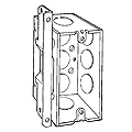
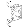
“A” Bracket: Positions handy
box against face and side of stud. Very rigid. |
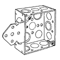
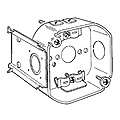
“B” Bracket: Face mounts on
front edge of wood stud. Use when space between
studs is limited. |
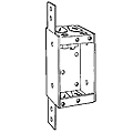
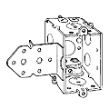
“D” Bracket: Allows box to be
mounted on either side of stud. |
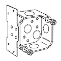
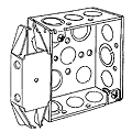
“FA” Bracket: Allows box to be
flush mounted to stud or joist. |
 |
 |
 |
 |
| “FM” Bracket: Mounts on flat side of stud. | “J” Bracket: Spurs, slotted holes for toe-nailing. Gauging notches at 3/8” and ½”. | “LB” Bracket: Face mounts on front edge of wood stud. Use when space between studs is limited. 5/8” offset to clear narrow door molding. | BOX-LOC® “MS” Bracket: Positions box on either side of stud. |
 |
 |
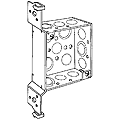 |
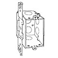
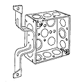
| “TS” Bracket: Side-mount bracket for octagon, square, switch and handy boxes. Gauging tabs and recessed nailing spur. Very rigid. | “W” Bracket: Positions box away from side of stud to clear the trim molding of a door frame. | “FH” Bracket: Side –mount bracket with hooks that drive into face of stud. |
| CLAMP TECHNICAL DATA AND STUD TYPE | |||||||
| CLAMP TYPE | RACEWAY TYPE | ||||||
| ARMORED CABLE (BX) | METAL CLAD CABLE INTERLOCKING (MCI) | NONMETALLIC SHEATHED CABLE | FLEXIBLE CONDUIT | ||||
| STEEL | ALUMINUM | STEEL | ALUMINUM | STEEL | ALUMINUM | ||
| "L" TYPE | #14-2 to #10-3 w/ground | ||||||
| "X" TYPE | #14-2 (.444 in outer diam.) to largest size to fit in clamp | #14-2 (.444 in outer diam.) to largest size to fit in clamp | .425 to .600 outer diam. | .425 to .600 outer diam. | 3/8" trade size | 3/8" trade size | |
| "#9 OR AOL" TYPE | #14-2 w/ground | ||||||
| "BN" TYPE | #14-2 to #10-3 w/ground | ||||||
| "Q" TYPE | #14-2 w/ground or #12-2 w/ground | ||||||
 |
 |
 |
 |
 |
| "L" TYPE | "X" TYPE | "#9 OR AOL" TYPE | "BN" TYPE | "Q" TYPE |
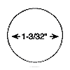
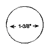
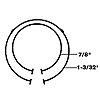
| KNOCKOUTS AND PRIOUTS | ||||
 |
 |
 |
 |
 |
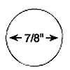
| ½” CONDUIT KO | ¾” CONDUIT KO | 1” CONDUIT KO | TKO CONDUIT KO |
CABLE PRIOUTS Always in pairs. |
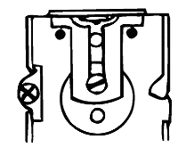
| PLASTER EARS | ||
| Adjustable plaster ears are included on many switch boxes and one octagon box. They are set forward 1/32”. |
|
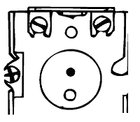 |
| ONE-SCREW EAR | TWO-SCREW EAR | |
| MOST OFTEN REQUESTED ARTICLES OF THE 1999 NATIONAL ELECTRICAL CODE® |
HOW RACO® PRODUCTS HELP COMPLETE THE INSTALLATION |
| 370-27 (a) Boxes at Lighting Fixture Outlets. Boxes used at lighting fixture outlets shall be designed for the purpose. | Our octagon boxes are designed for direct mounting of light fixtures. Device boxes are designed for the mounting, (by #6-32 screws), of devices such as snap-switches and receptacles. They are not suitable for support other than for very lightweight devices, such as a smoke alarm unit. (See Article 410-16) or wall fixtures 6 lbs. or less [See 370-27(a) exception]. |
| 370-10 Space for Conductors. Canopies and outlet boxes taken together shall provide adequate space so that fixture conductors and their connecting devices can be properly installed. | When calculating the minimum cubic inch requirements for an outlet box, the canopy may be included in the calculation. However, the canopy of the fixture/fan needs to be marked with the cubic inch capacity. The volume of an unmarked canopy may be used at the discretion of the local authority having jurisdiction. |
| 370-27 (c) Boxes at Fan Outlets. Outlet boxes shall not be used as the sole support for ceiling (paddle) fans. Exception: Boxes listed for the application shall be permitted as the sole means of support. | At any ceiling outlet that is intended to have a ceiling (paddle) fan installed, a UL Listed outlet box rated for ceiling fan support must be used. RACO offers a complete line of products designed for various applications and mounting needs. |
| 370-27 (b) Floor Boxes. Boxes listed specifically for this application shall be used for receptacles located in the floor. Exception: Boxes located in elevated floors of show windows and similar locations where the authority having jurisdiction judges them to be free from physical damage, moisture, and dirt. | Only boxes that are UL Listed for the application may be fastened into the floor. RACO® floor boxes are in Section C in this catalog. |
| 410-16 (a) Means of Support – Outlet Boxes. Where the outlet box or fitting will provide adequate support, a fixture shall be attached thereto or be supported as required by Section 370-23 for boxes. A fixture that weighs more than 50 pounds (22.7kg) shall be supported independently of the outlet box. | All outlet boxes that are intended to be used with fixtures are tested in accordance with UL Standards 514-A for steel boxes, 514-C for plastic boxes. The test does provide an ample margin for safety. |
|
422-18 Support of Ceiling Fans.
(a) Ceiling Fans 35 lbs. or Less.
Listed ceiling fans that do not exceed 35 pounds
in weight, with or without accessories, shall be
permitted to be supported by outlet boxes
identified for such use and supported in
accordance with Sections 370-23 and 370-27.
(b) Ceiling Fans Exceeding 35 lbs.
Listed ceiling fans exceeding 35 pounds in
weight, with or without accessories, shall be
supported independently of the outlet box. See
Section 370-23. |
If the outlet box is UL Listed for ceiling fan support, the maximum fan weight that can be supported is 35 pounds unless otherwise marked. The RACO® ceiling fan box (7120) is UL Listed for 70 lbs. RACO® ceiling fan outlet boxes use hardened screws for support of the fan. Captive star lock-washers prevent the screws from loosening, providing a safe and secure installation. |
| 800-52 (c) Installation of Communications Wires, Cables, and Equipment – Electric Light or Power Circuits. Communications conductors shall not be placed in any raceway, compartment, outlet box, junction box, or similar fitting with conductors or electric light or power circuits or Class 1 circuits. | When power and voice/data are brought to one enclosure, a means of dividing the wiring is required. RACO® has a variety of metallic and nonmetallic low voltage partitions. |
RACO floor boxes are ideally suited for heavy floor traffic applications, such as shopping malls, retail stores, banks and schools. Floor boxes are installed in poured concrete floors and are fed with conduit. RACO’s complete line includes both single service and three-service (power and voice/data) floor boxes, which are available in cast iron, stamped steel and PVC plastic. Floor box covers and carpet flanges are offered in brushed brass and textured thermoplastic in two designer colors, ivory and gray. RACO floor boxes:
- Are used in branch circuit wiring
- Accommodate wiring devices such as receptacles for voice/data
- Provide excellent protection for wiring system or devices
- Must be closed with a cover
- Permit access to conductors for maintenance
This type of box has no means for adjustment. It is usually installed in wooden floors or used for retrofit in concrete.
RACO quality non-adjustable floor boxes feature:
- Rugged cast iron for strength and ground continuity
- Factory-installed ground wire
- Simple one-piece floor box design offers flexibility for power outlet or voice/data outlets
- Conveniently positioned conduit entries are tapped and plugged
Fully-Adjustable Floor Box Features
This type of box has leveling screws for height and leveling adjustments to be made before the concrete is poured, and final leveling adjustments after the concrete is poured. The maximum leveling adjustment is a 7° tilt.
Fully-Adjustable Floor Boxes feature:
- Concrete-tight floor boxes for use in power or voice/data
- Cast iron boxes classified as water-tight and concrete-tight, typically used below grade where excessive moisture is present
- Choice of materials – stamped steel or cast iron
- Cast iron floor box including factory-installed ground wire, and multiple gang boxes with one ground wire per gang
- Multiple gang boxes provided with low voltage partitions
- Ample wiring space for any combination of power outlet or voice/data outlets
Standard Materials
- Nonmetallic floor box is made of heavy-duty PVC (Polyvinyl chloride) compound. Base material is recycled
- Steel floor boxes are made of .0625-inch-thick steel
- Cast iron floor boxes are made from cast iron having a high tensile strength
- Solid brass covers and carpet flanges
- Nonmetallic floor box covers and carpet flanges are made of high-strength thermoplastic (ABS)
Standard Finishes
- Natural gray finish on nonmetallic floor box
- Nonmetallic floor box covers and carpet flanges are available in gray and ivory
- Steel boxes have a zinc coating
- Cast iron floor boxes have a gray powder coat paint finish
- Solid brass covers and carpet flanges have a brushed finish
Floor boxes are subject to the same code requirements and minimum conductor fill requirements as other boxes. RACO floor boxes carry the following compliances:
- UL Standard 514-A, file E4872
- Boxes are listed for their Electrical Applications (Electrical Codes), UL Green Book
- U.S. Federal Specification and Standards W-C-583B
- Federal Manufacturer’s number 28488
Reference Data
Installing a fully-adjustable floor box in a poured concrete floor: RACO provides with all box assemblies or flanges a metallic concrete cover. The concrete cover permits pouring concrete to the top of the box. The cover is then easily removed after the pour. To install a box:
- Locate box and install conduit in accordance with local codes
- Secure box to reinforcing bar (mesh)
- Make pre-pour height and leveling adjustments
- Grease inside of cement cover and install on box
- Grease outside of cement cover
- Apply bead of grease on exposed portion of adjusting collar
- Tape cement cover to box
- Pour concrete
- After the concrete has set, remove the concrete cover
- Pull wires and install wiring device
- Make final pour adjustments, and grout around the box if required
- Install cover plates and/or accessories
| SUMMARY OF THE MOST OFTEN REQUESTED ARTICLES OF THE 1999 NATIONAL ELECTRICAL CODE® |
HOW RACO PRODUCTS HELP COMPLETE THE INSTALLATION |
| 210-52 (a) Dwelling Unit Receptacle Outlets – General Provisions. In every kitchen, family room, dining room, living room, parlor, library, den, sun room, bedroom, recreation room, or similar room or area of dwelling units, receptacle outlets shall be installed so that no point along the floor line in any wall space is more than 6 feet, measured horizontally, from an outlet in that space, including any wall space 2 feet or more in width and the wall space occupied by fixed panels in exterior walls, but excluding sliding panels in exterior walls. The space afforded by fixed room dividers, such as free-standing bar-type counters or railings, shall be included in the 6-foot measurement. |
Every 6 feet along the wall surface there should
be a receptacle outlet regardless of the room
within the dwelling. The purpose of this Article
is to eliminate extension cords that are used
within the dwelling. Electrically overloaded
extension cords are often a source of fires.
Installation of a RACO floor box may help
alleviate the need for extension cords by
locating receptacles where no wall outlets are
installed.
Receptacle outlets in floors can be counted
as part of the required number of receptacles if
they are within 18 inches of the wall. |
| 250-146 Connecting Receptacle Grounding Terminal to Box. An equipment bonding jumper shall be used to connect the grounding terminal of a grounding-type receptacle to a grounded box. Exception (c): Floor boxes designed for and listed as providing satisfactory ground continuity between the box and the device. | All RACO floor boxes are designed and listed for having ground continuity without an equipment bonding jumper. RACO does provide on all of its cast floor boxes a factory-installed ground wire. |
| 370-27 (b) Outlet Boxes –Floor Boxes. Boxes listed specifically for this application shall be used for receptacles located in the floor. Exception: Boxes located in elevated floors of show windows and similar locations where the authority having jurisdiction judges them to be free from physical damage, moisture, and dirt. | Only boxes that are UL Listed for the application may be fastened into the floor. |
| 800-52 (c) Installation of Communications Wires, Cables, and Equipment – Electric Light or Power Circuits. Communications conductors shall not be placed in any raceway, compartment, outlet box, junction box, or similar fitting with conductors of electric light or power circuits or Class 1 circuits. | This Article applies when power and voice/data are brought to one enclosure. A means of dividing the wiring is required. Voltage dividers are available for the following floor box types: PVC floor box and rectangular fully-adjustable. |