EARLY DESIGN RHODES PIANOS - DIMENSIONAL STANDARDS AND ADJUSTMENTS
- Key Dip. Key Dip and Hammer travel are controlled by the height of the Action Rail. Key Dip is the term used to describe the downward limit of travel of the Key when depressed. 3/8" (9.525mm) is ideal. This is controlled by means of shims
(Figure 10-1) placed between the Action Rail and the Key Frame. To adjust, remove the entire Action from the box. Along the back of the Key Frame under the Action Rail will be five wood screws. Remove these, then either remove shims or add shims depending upon whether you wish to reduce or increase the Key Dip.
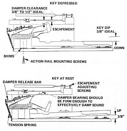
Figure 10-1. RHODES Early Design Single Key Views
- Damper Control. The Damper ideally clears the Tine by at least 3/8" to 1/2" (9.525mm to 12.7OOmm) when the Key is depressed. Conversely, when the Key is at rest, the Damper should bear firmly on the Tine in order to effectively damp the sound.
To maintain this relationship, there are two adjustments possible.
- Tension. Refer to Page 4-4.
- Alignment. Refer to Page 4-4.
- Escapement. Escapement is the word used to describe the distance between the striking edge of the Hammer Tip and the Tine when the Key is fully depressed. This distance varies from between 3/16" (4.762mm) and 3/8" (9.525mm) in the Bass section to between 1/16" (1.588mm) and 1/8" (3.175mm) in the Mid section and between 1/32" (0.794mm) and 3/32" (2.381mm) in the Treble section. The shorter the Escapement distance, the more sensitive the touch.
The Escapement distance could be called the "free throw" area. In other words this is the area of Hammer travel after the energy imparted by the touch is no longer effective. In order to understand the philosophy, suppose the Escapement distance
were 1/2" (12.7OOmm). Under this condition, it would require an extremely sharp blow to impart enough acceleration to the Hammer to enable it to reach the Tines. Now reverse the situation, suppose that we reduce the Escapement to zero. The lightest feather touch will produce a sound. However, sustained finger pressure on the Key will cause the Hammer to smother the sound. Now back off a bit. Raise the Escapement to the point where the Hammer can no longer smother the sound. This becomes the ideal setting.
To achieve the ideal Escapement setting, there are several adjustments possible depending upon the vintage Piano involved.
- To decrease the Escapement distance, compress both Escapement Adjusting Springs (Figure 4-4). This will lower the entire Tone Bar Assembly thus reducing the gap. Once this is accomplished re-establishment of Timbre and Volume setting is done in the usual way.
- If the Escapement is excessive throughout the entire Piano, proceed as follows:
- Remove the two Side Support Blocks (Figure 10-2).
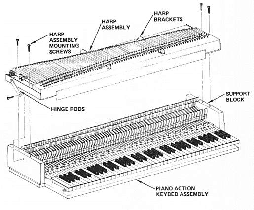
Figure 10-2. RHODES Early Design Harp/Action Assembly - Exploded View
- Using a table saw, shave off the desired amount from the top surface of each Block, approximately 1/16" (11.588mm) to 1/8" (3.175mm).
- Replace the Assembly, then reset the Dampers for maximum performance.
- An alternate method of accomplishing the same thing is to remove all Hammer Tips, add a Shim, then replace the Tips, as outlined on Pages 9-2 and 9-3. This procedure, while perhaps a bit more tedious, requires no equipment nor re-adjustment of Dampers.
As also is the case in string pianos, the Escapement distance in the Bass section should be greater than in the middle and upper sections. This requirement is even more pronounced in our Instrument due to the wide arc of Tine movement encountered. Escapement distance on Tone Bar 1 could be 3/8" (9.525mm). Insufficient Escapement in this area invites "double stroking" with an accompanying disturbing sound.
Signal Strength:
Originally the 73 Pickup Coils were joined in a series/parallel arrangement as shown in Figure 10-3.
Figure 10-3. RHODES Original Pickup Coil Series/Parallel Arrangement
Later, basic voltage output was quadrupled by changing the series/parallel arrangement as shown in Figure 10-4.
Figure 10-4. RHODES Modified Pickup Coil Series/Parallel Arrangement
This change can be made on any of the older Pianos simply by re-routing the bus wires as shown in Figure 10-5. The output impedance then becomes approximately 2500 ohms.
Figure 10-5. RHODES Bus Wire Re-Routing Diagram
TOC - 1 - 2 - 3 - 4 - 5 - 6 - 7 - 8 - 9 - 10 - 11