UPPER WALL MOUNTED CABINETS
Click on any picture to see full size.
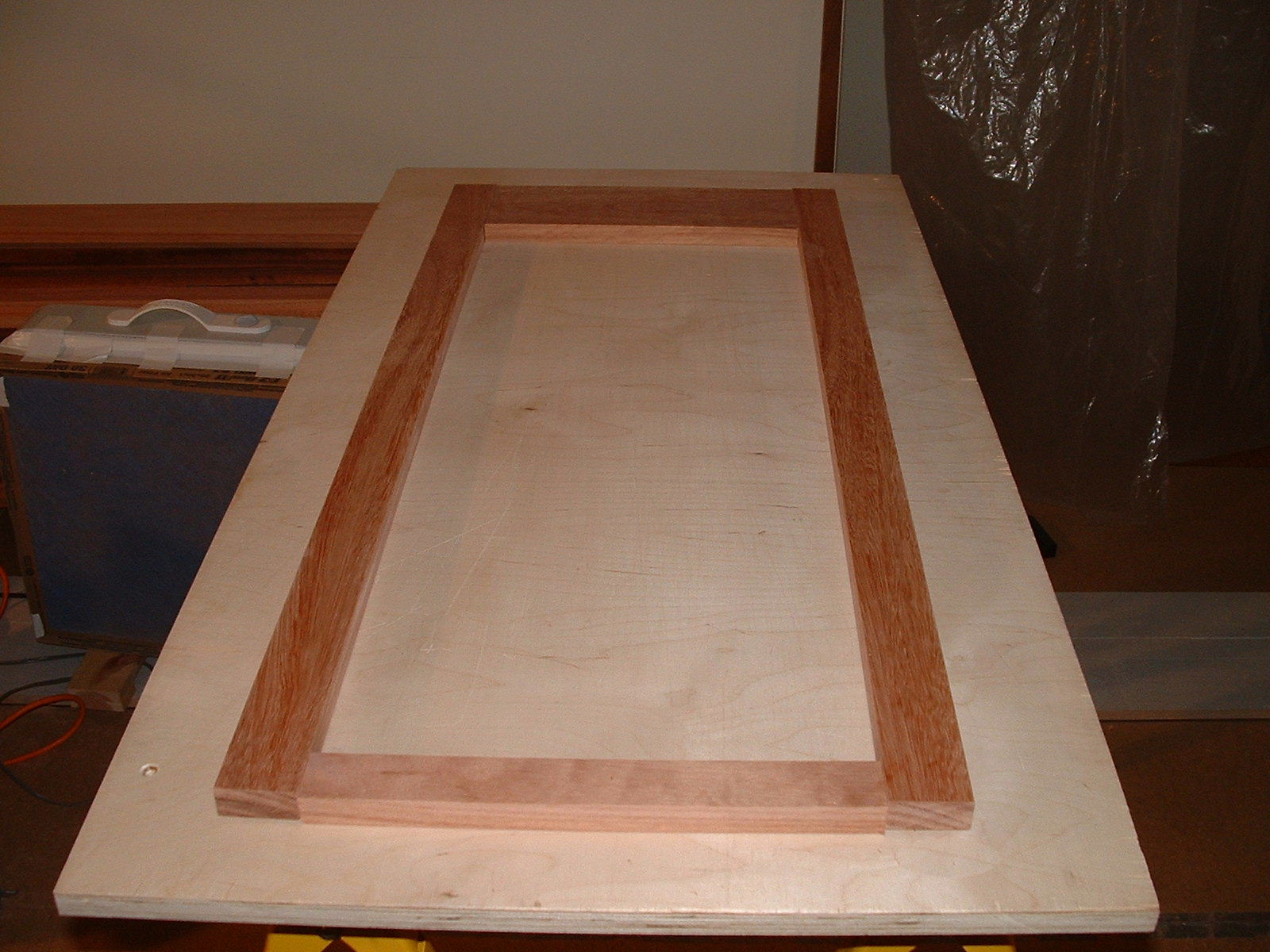
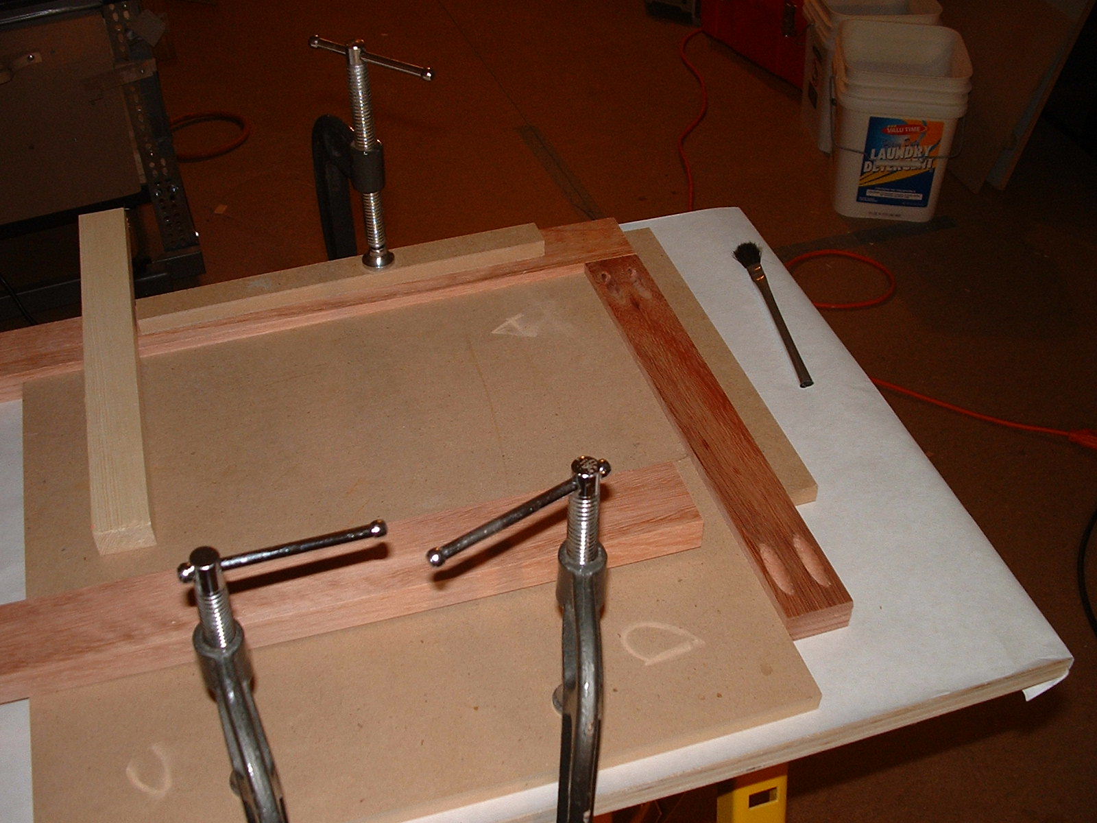
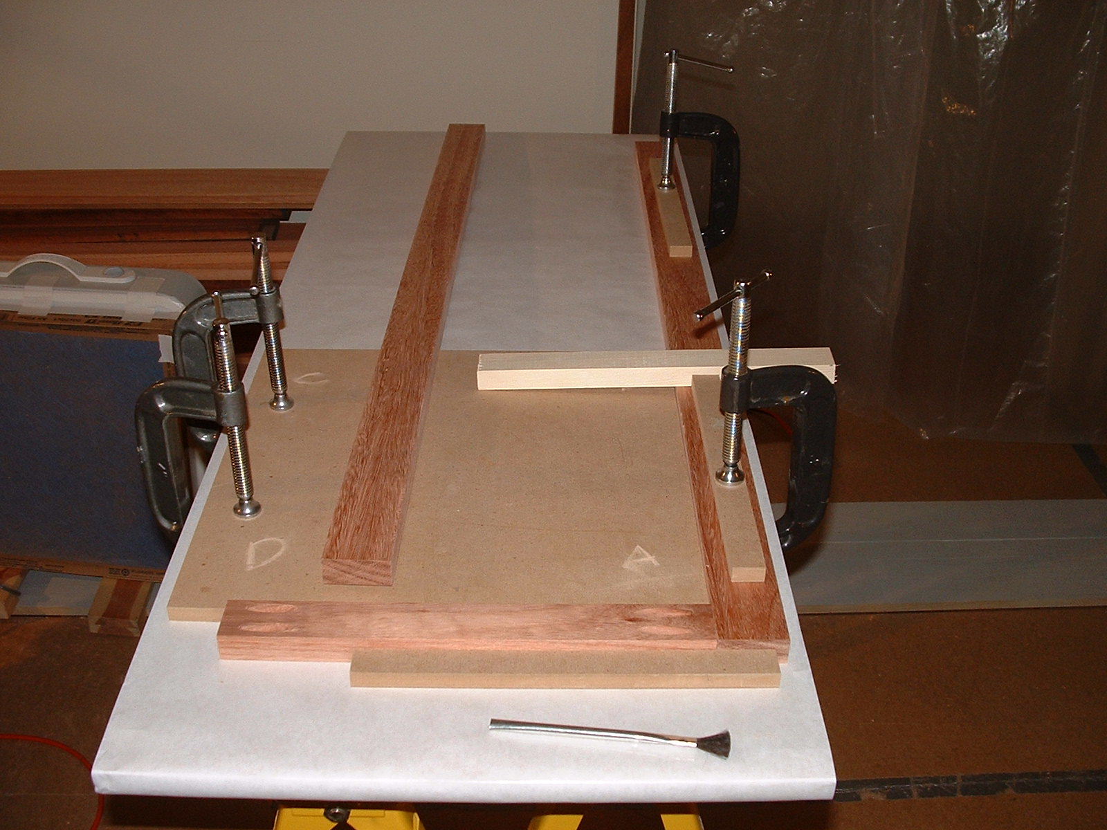
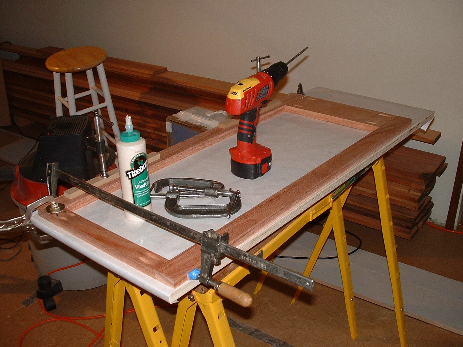
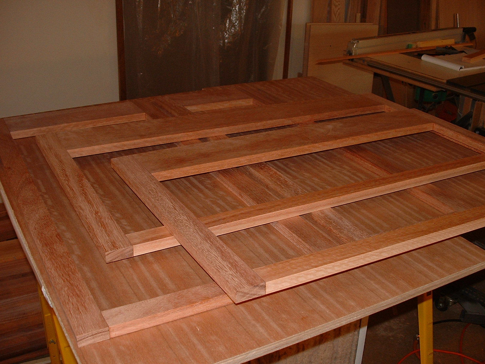
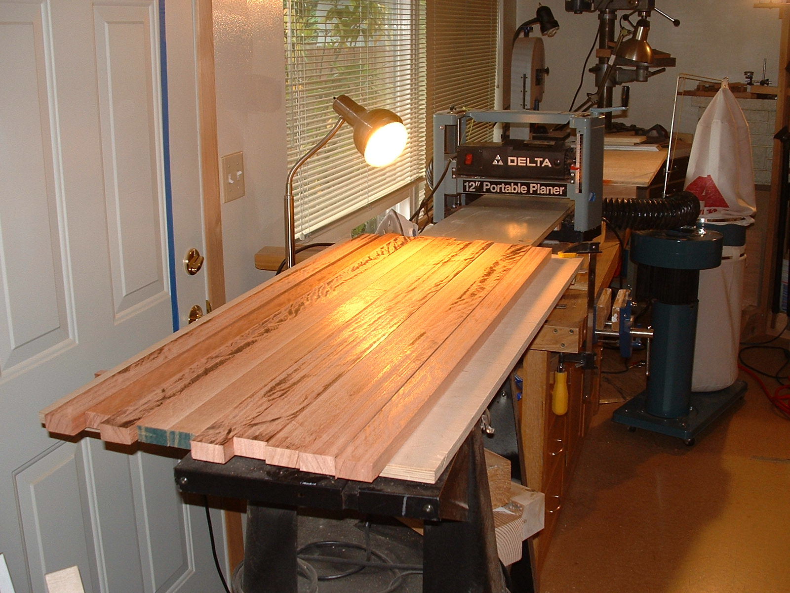
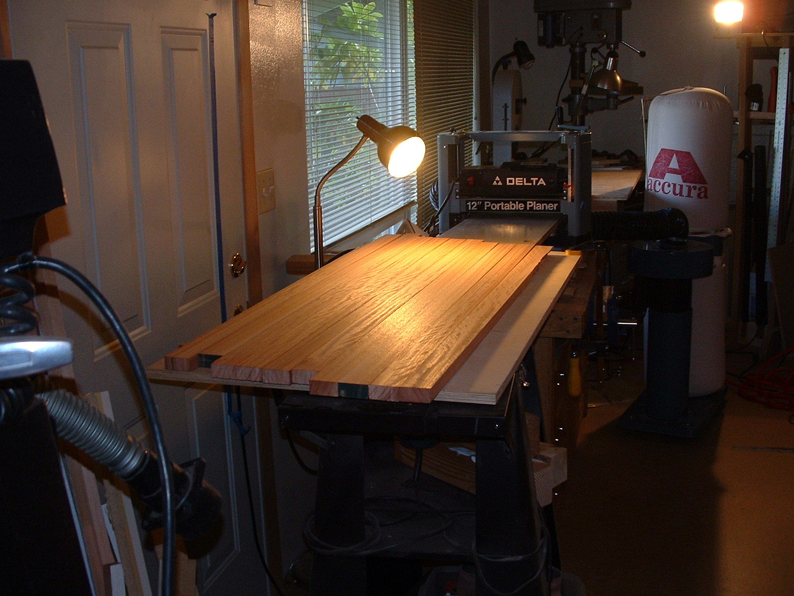
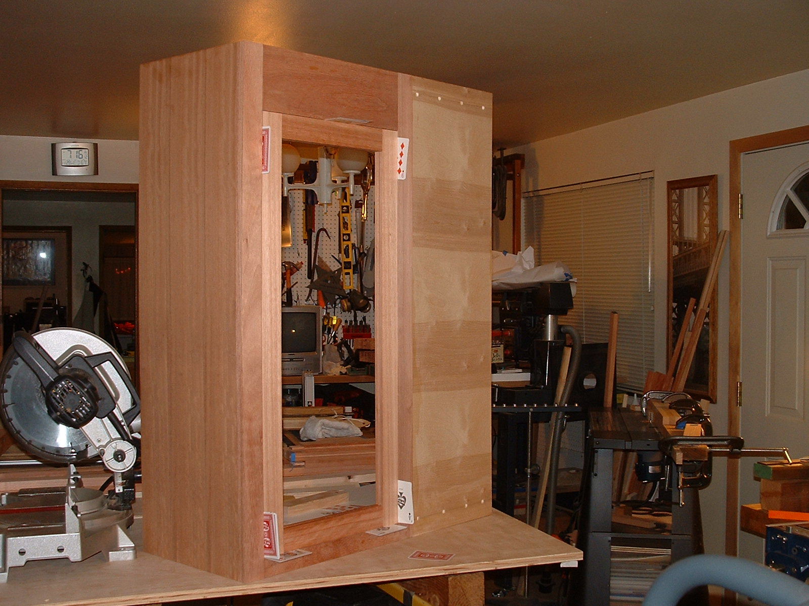
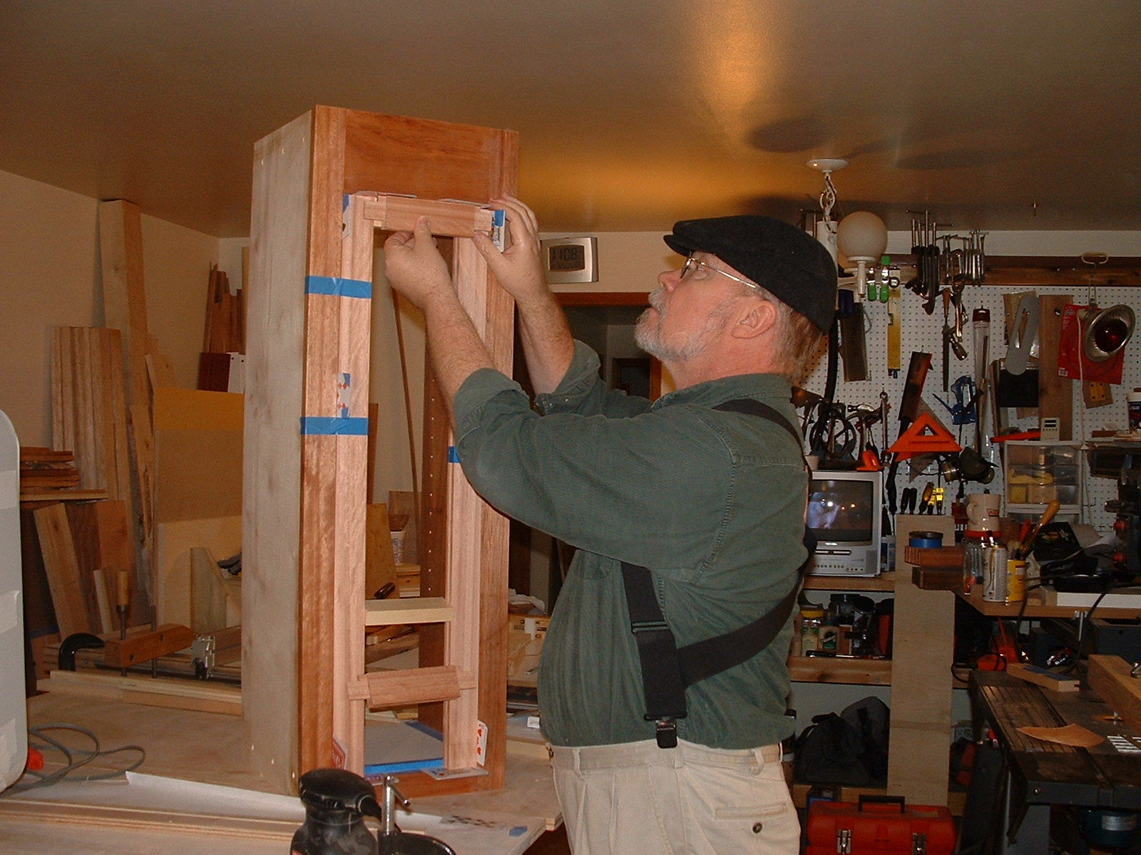
After cutting selected boards to length I lay them out in the first picture below. The second, third and fourth pictures show screw and glue assembly using the Kreg Pocket Hole Jig. The fifth picture is the assembled face frame standing free and upright. I guess if it can stand like that, its mostly square.
:
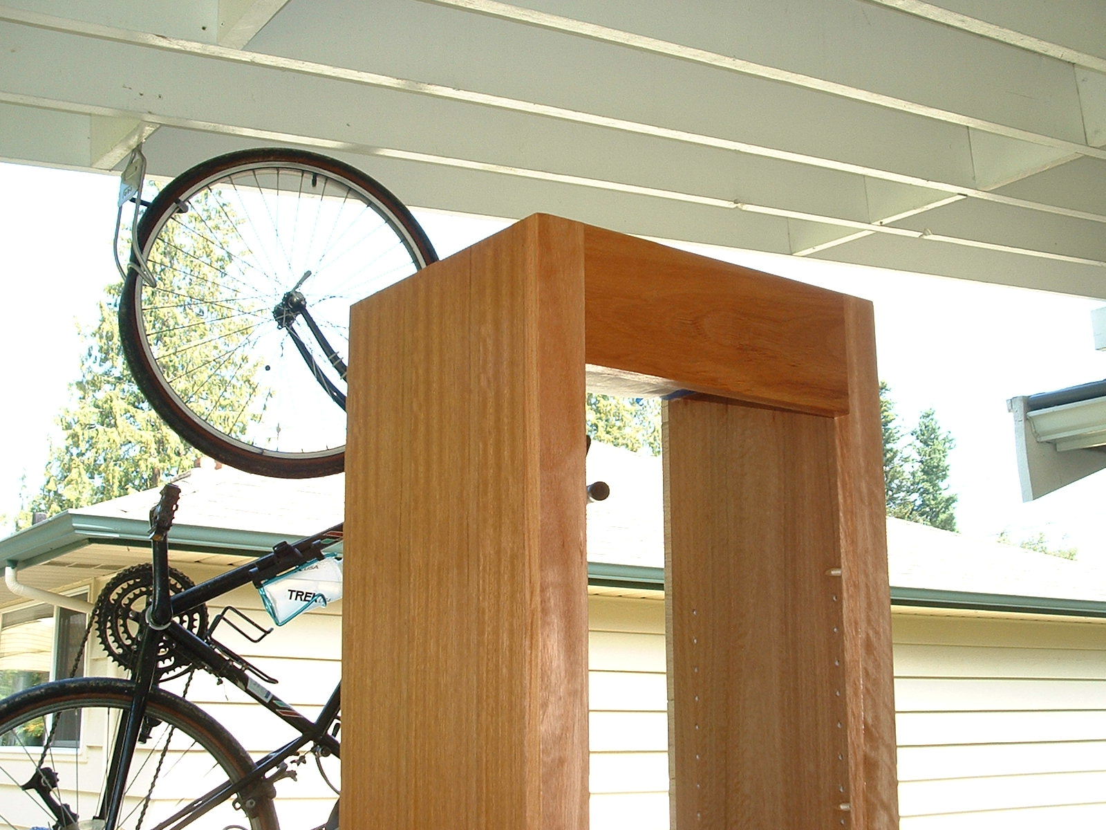
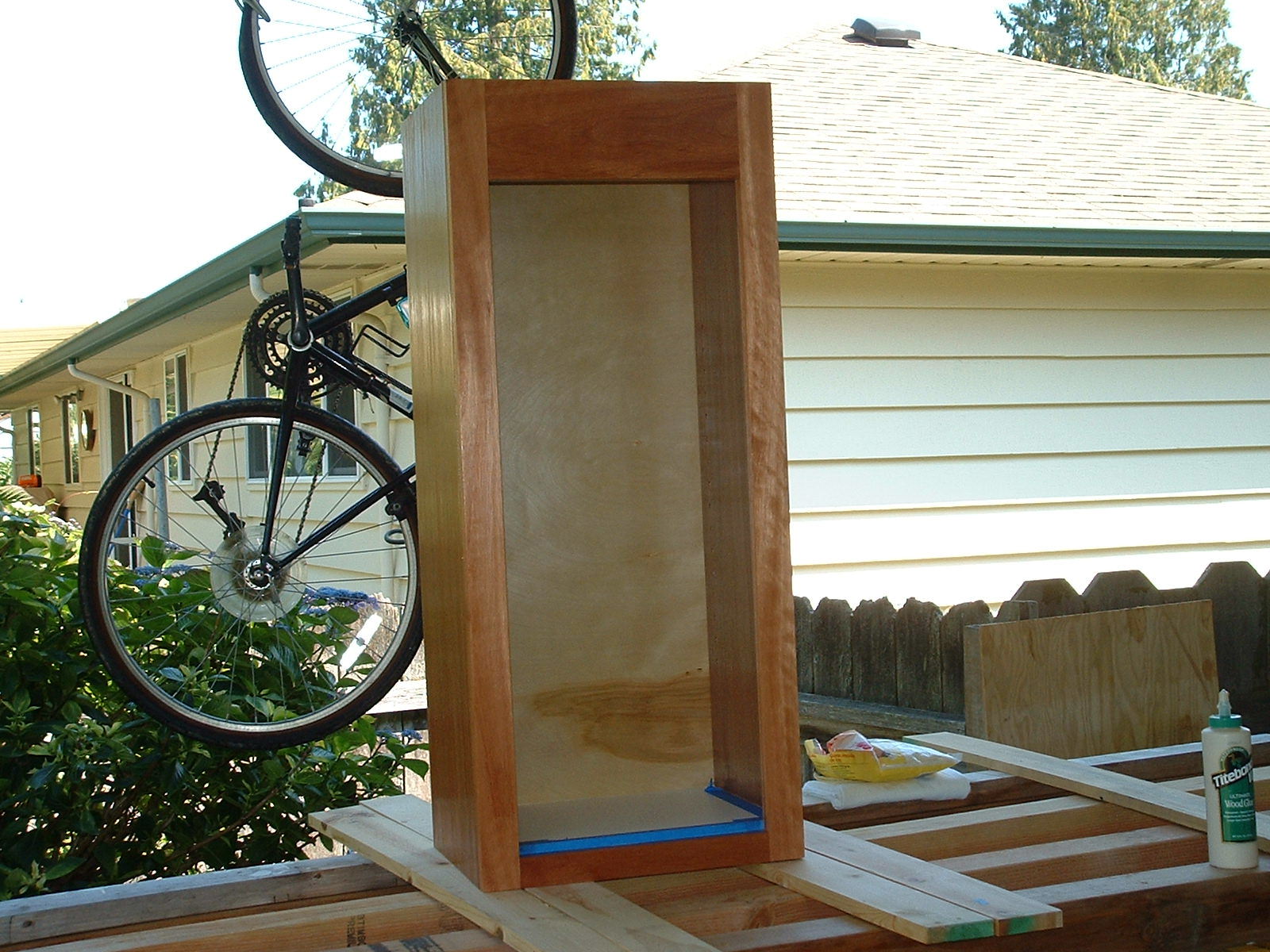
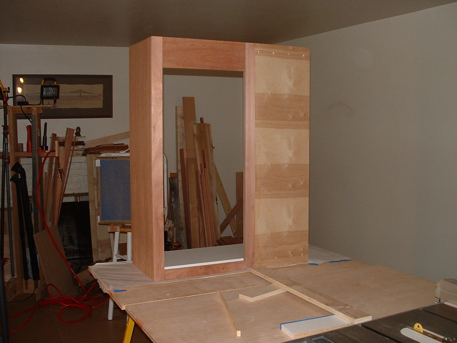
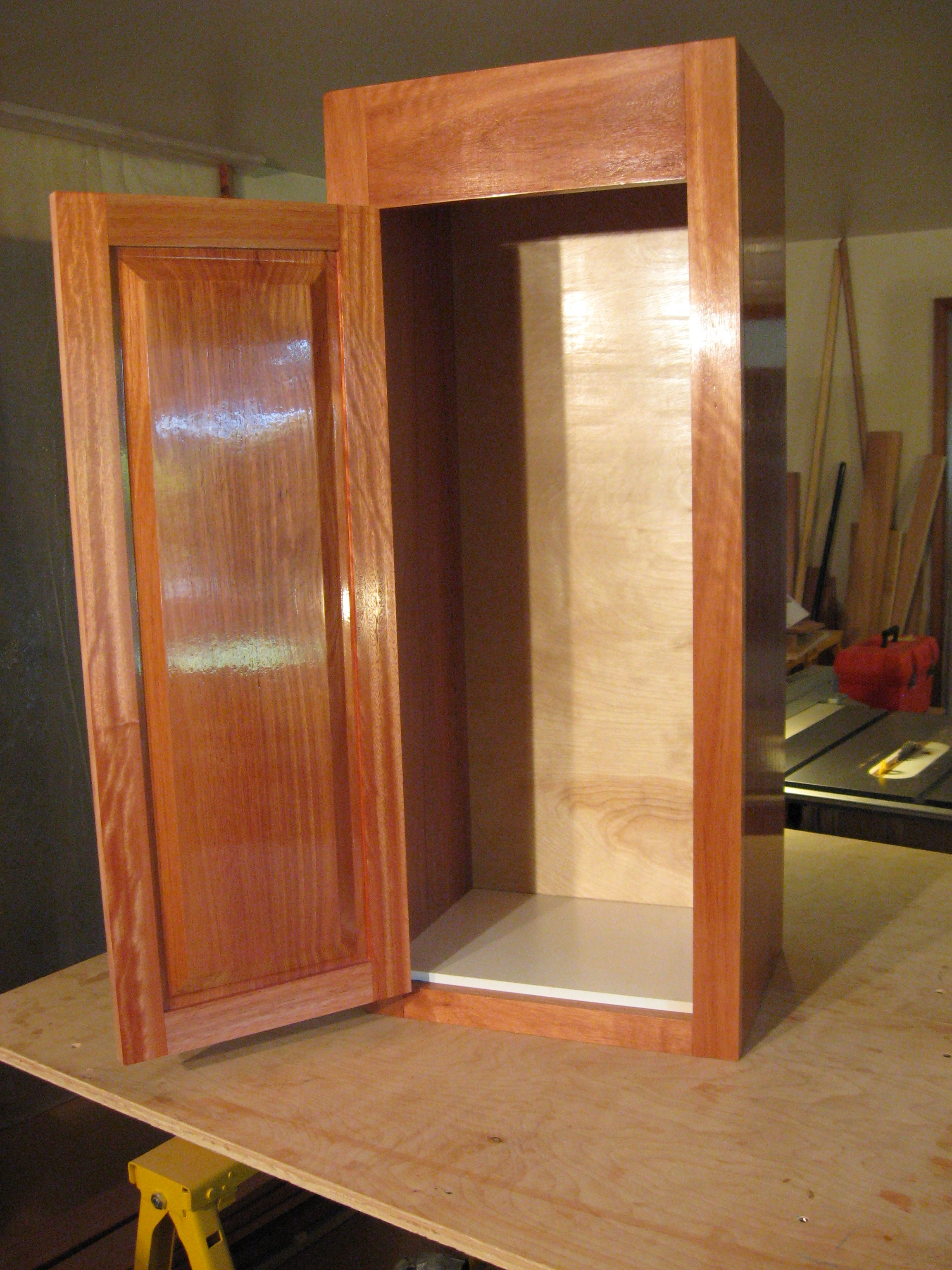
Cabinet carcass preparation starts with sizing and cutting the side panels. These panels receive a 1/2" deep dado along the top and bottom. The dado is a structural component that prevents torsional movement after assembly. This dado will accommodate the bottom shelf and cabinet top. The bottom shelf will be 1/2" above the bottom face frame rail and act as a door stop. This also provides the 1-1/4" space under the cabinets to hide the under cabinet lights. The panels also receive a 1/2" deep 1" wide rabbet along the back edge to accept the 3/4" birch plywood back panel. The 1/4" remaining edge along the back is used to facilitate the scribed fit to the wall during installation.
:
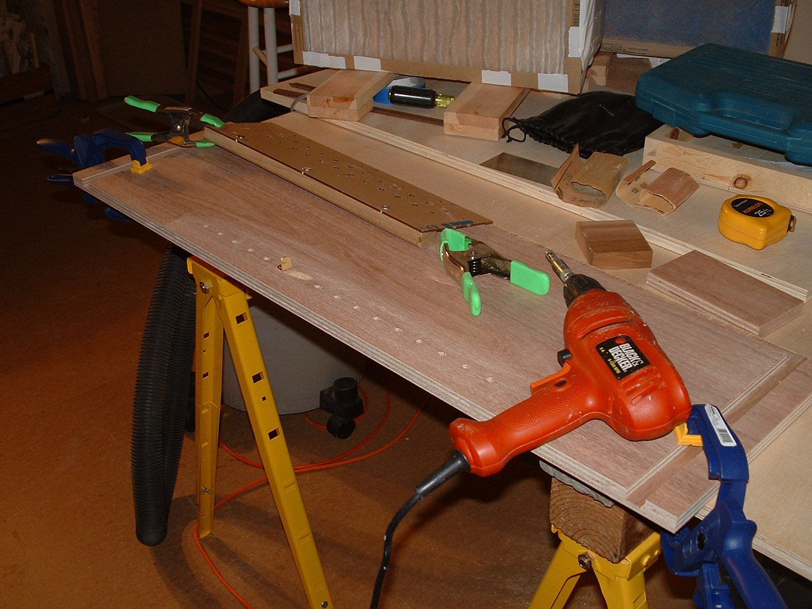
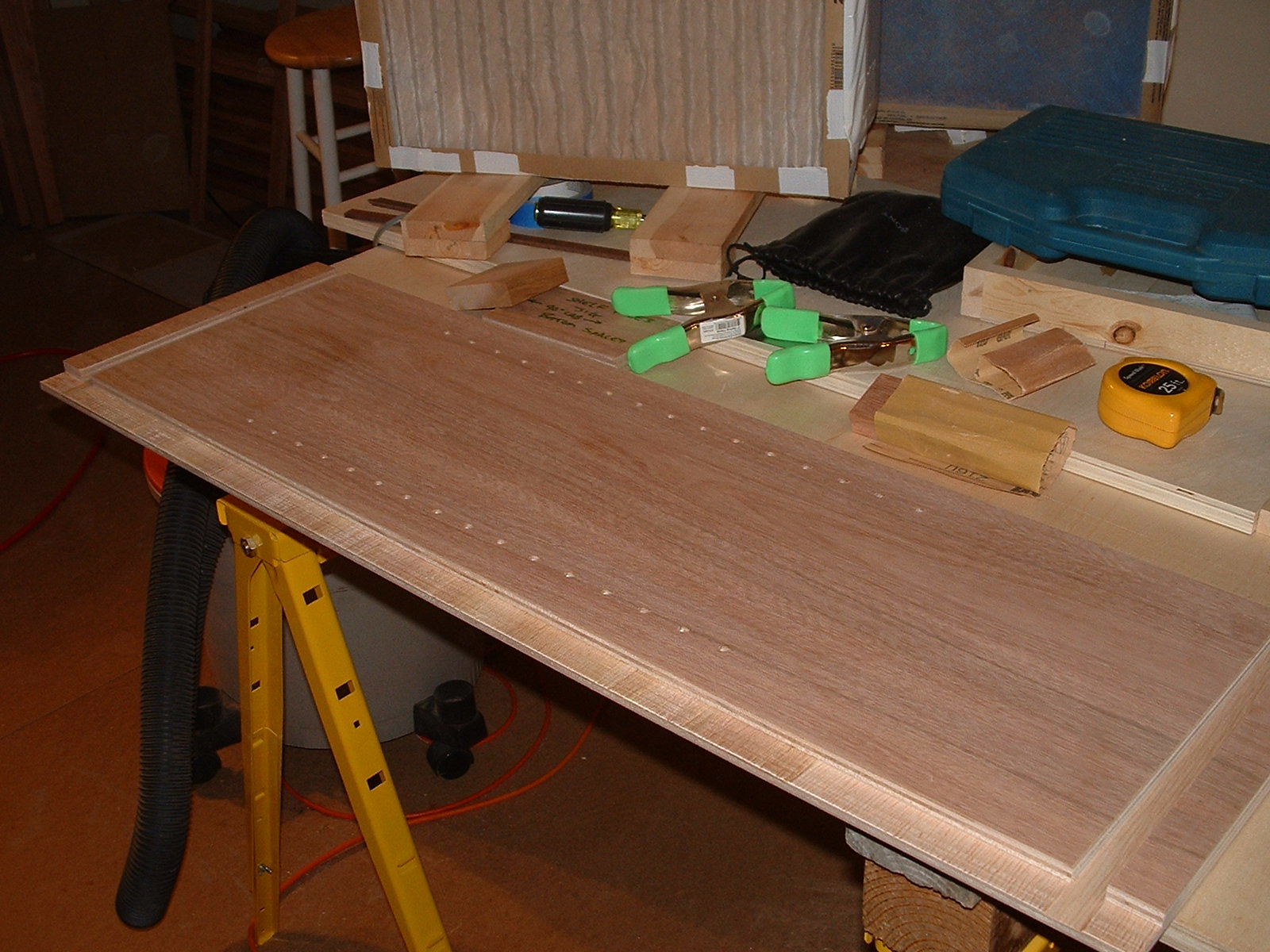
The two middle shelves in the cabinet will be adjustable. A jig is used to space and align the 1/4" holes along the front and rear of the side panels. These holes will accept the brass shelf pins used to support the shelves. The drill has a 1/4" Vix Bit in the chuck. This bit fits in the jig and centers the hole that is drilled.

:
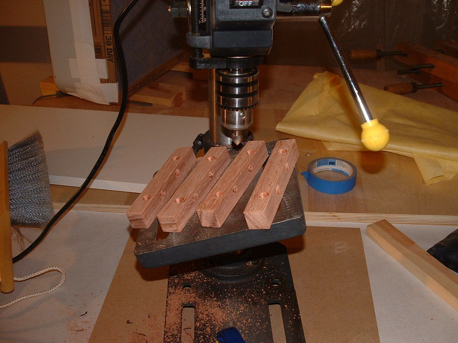
Pocket holes are drilled into both side panels. These will be used to glue and screw the sides to the face frame. The 3/4" x 5" blocks are to hold together the sides with the top and bottom. They are placed above the top and below the bottom so they are out of site. The countersunk holes are at 15 degrees to allow the use of an electric driver to screw and glue them in place.

:
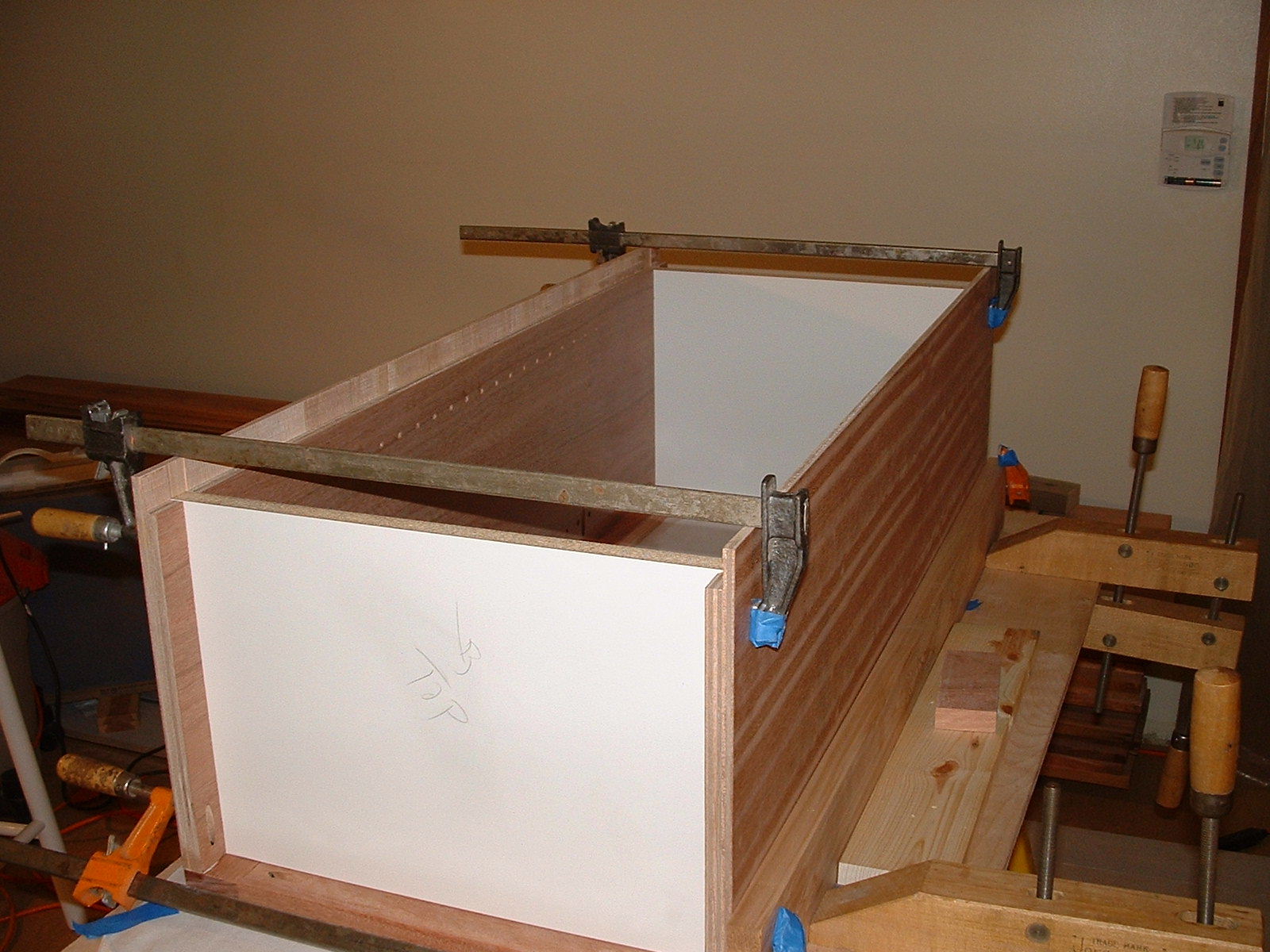
Assembly
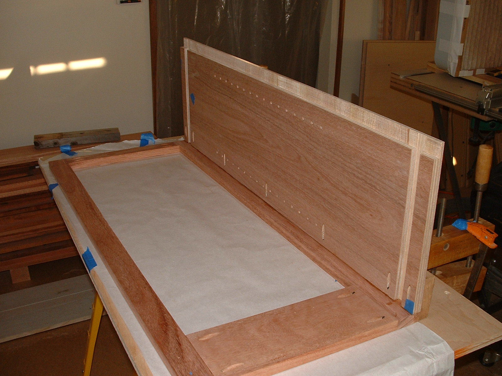
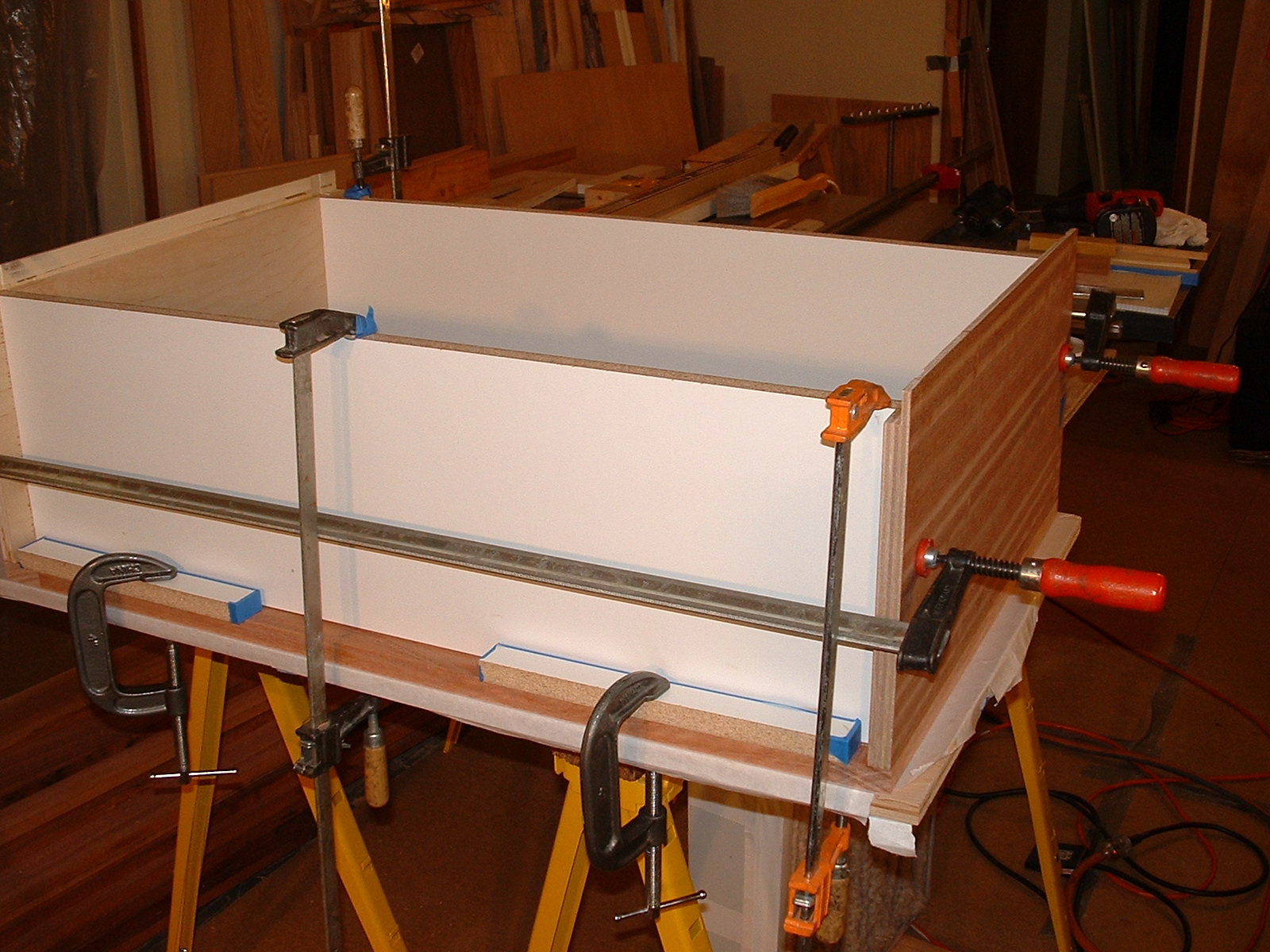
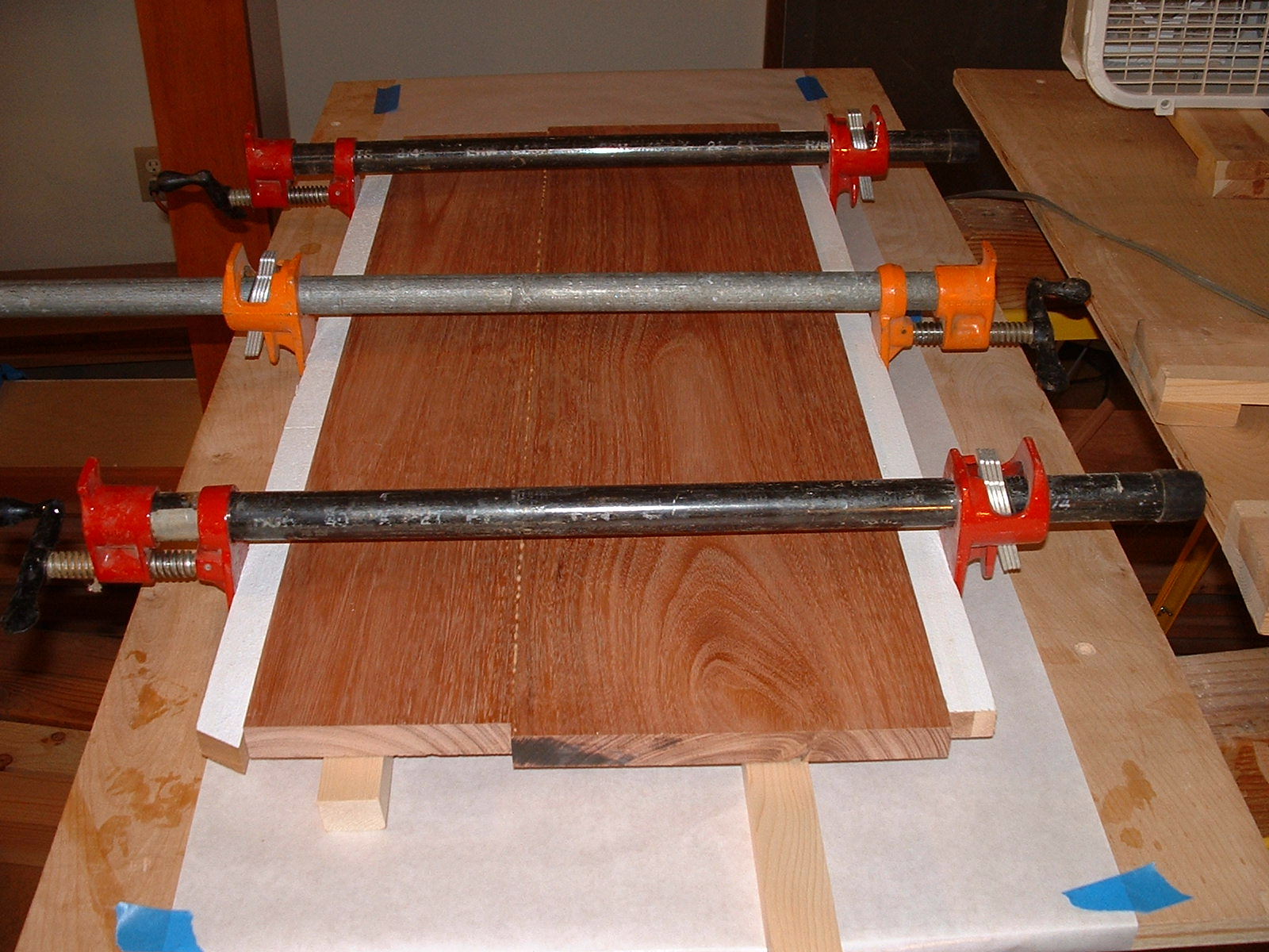
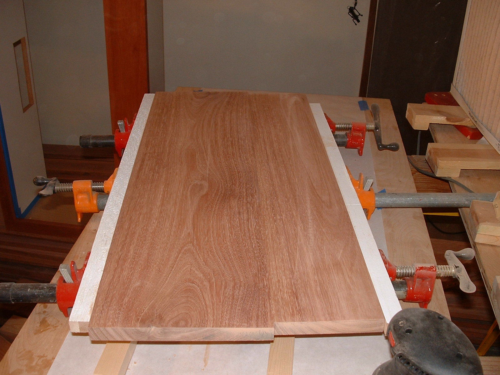
The first two boards always seem to give me trouble. After I get them together, I glue the top and bottom into the dado. After they are dried I then attach the other side. You would think that the 10 minutes open time for wood glue would be enough. IT never is.
:
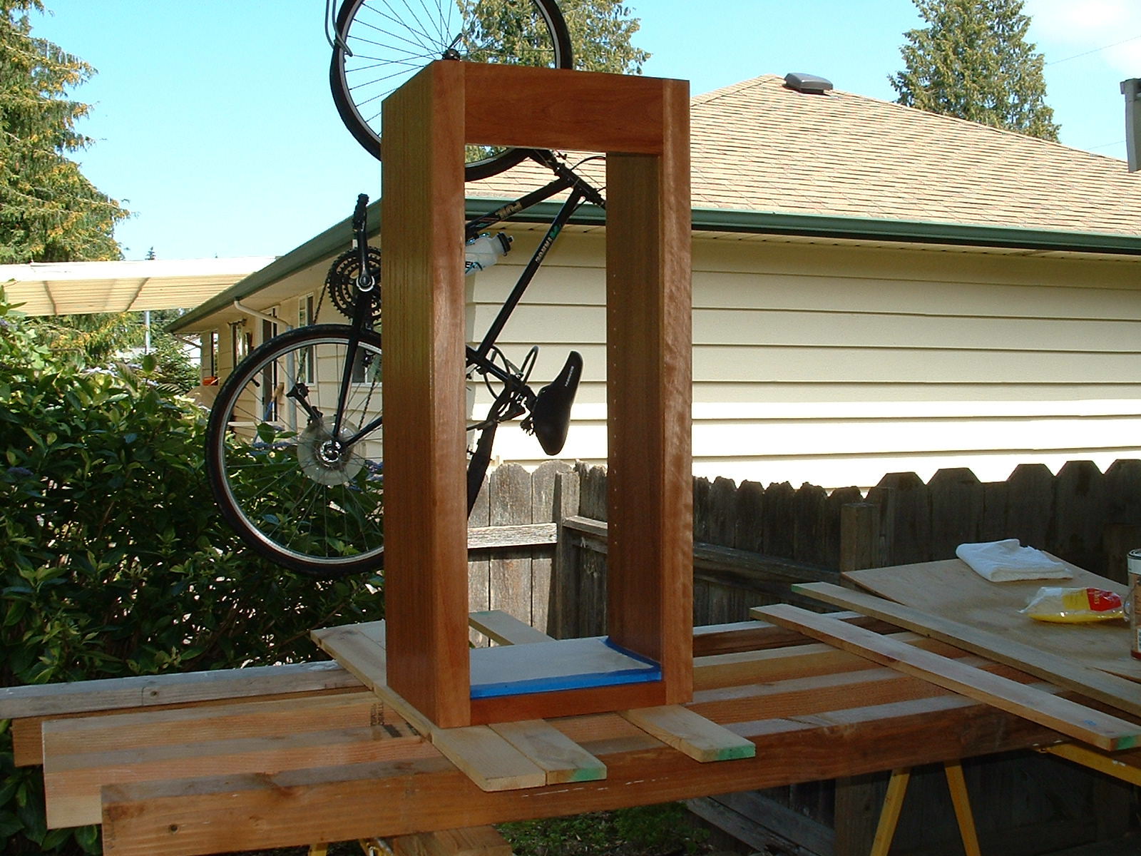
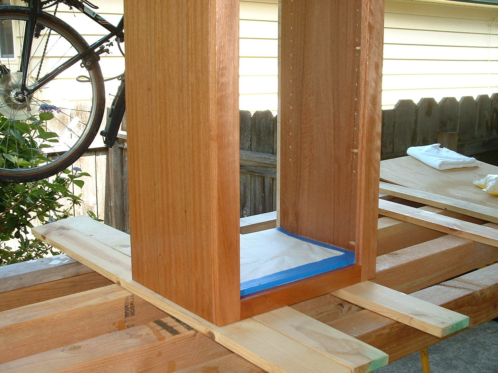
Sanding Sealer
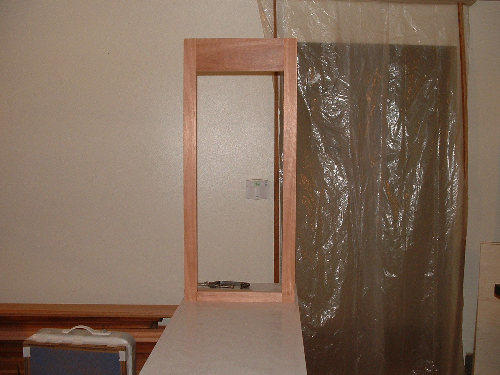
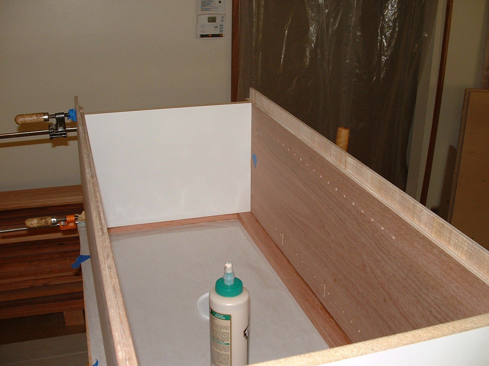
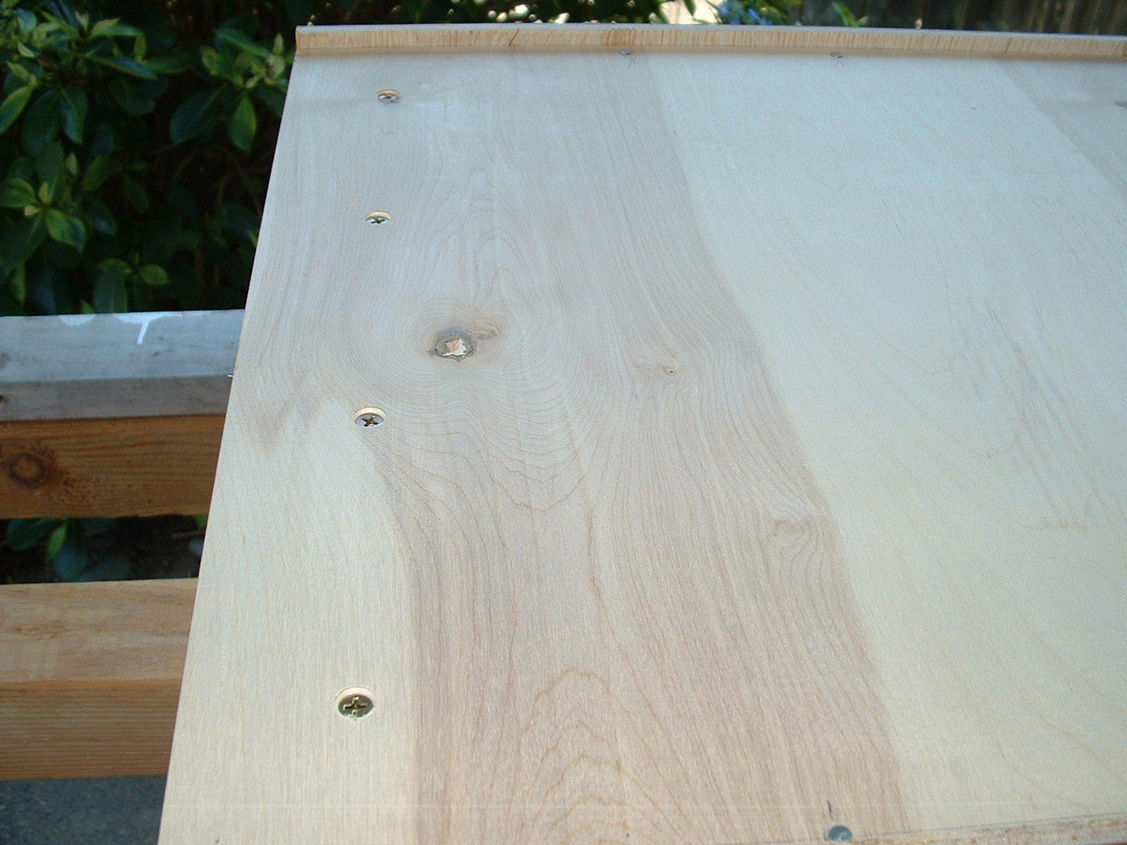
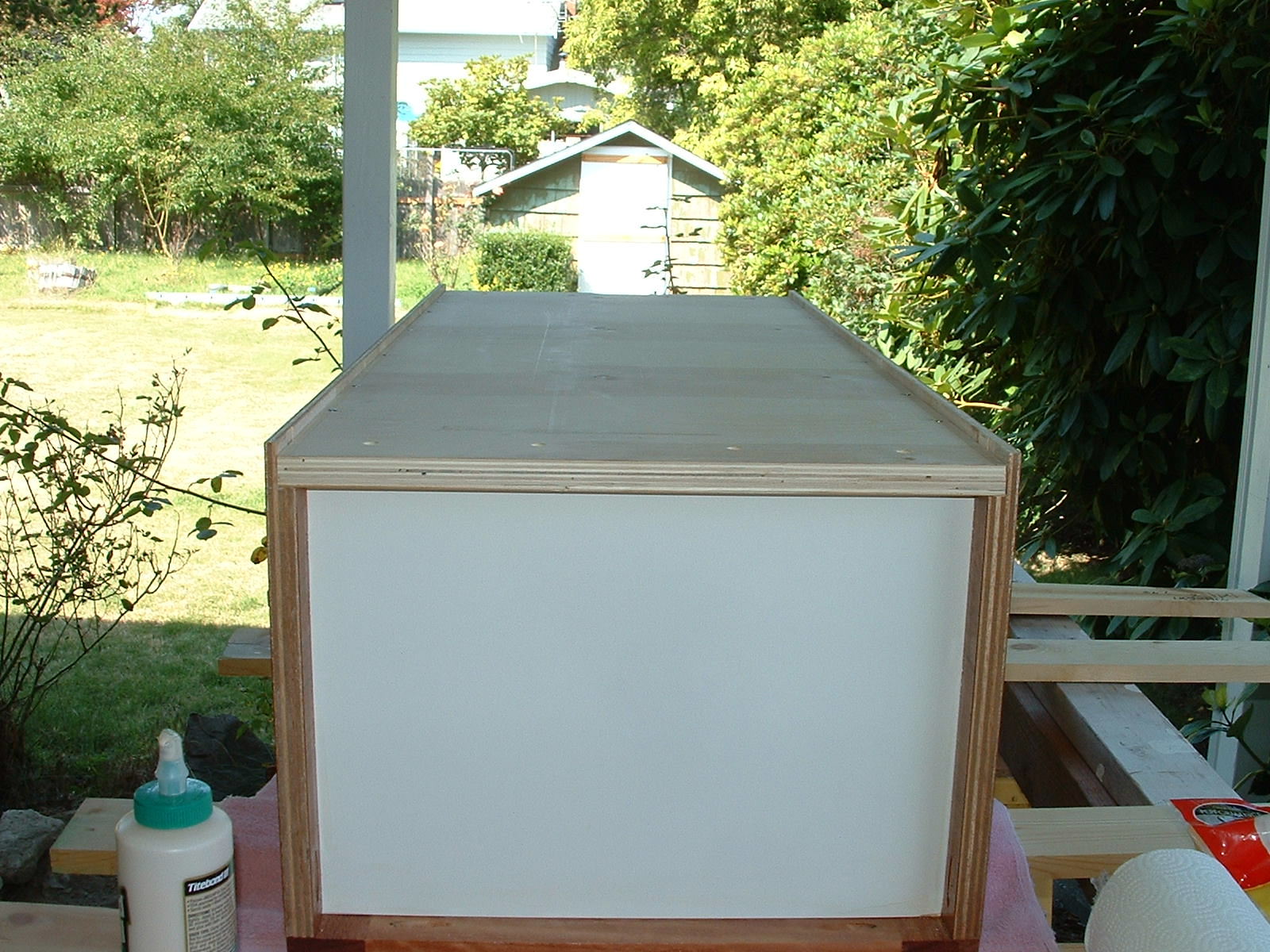
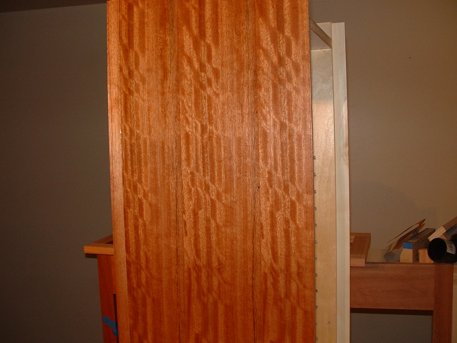
The first few coats are Zinsser SeatCoat Universal Sanding Sealer, a de-waxed shellac, to prepare the wood prior to the oil based polyurethane. See Technical Data Bulletin PDF file here: SealCoat. Between coats the surfaces are sanded with as high a grit as 600. Inside the melamine at the bottom and top are masked off. The shellac is applied with a rag. These large surfaces are difficult to finish. All the weight of the cabinet and its contents will hang on a few screws through the back of the cabinet into the wall. The 3/4" birch plywood back is cut to fit. The screws along the top and bottom are predrilled and countersunk. A dozen holes for the 4d nails along the sides are predrilled and Titebond glue is used.
:
Now Make More Cabinets
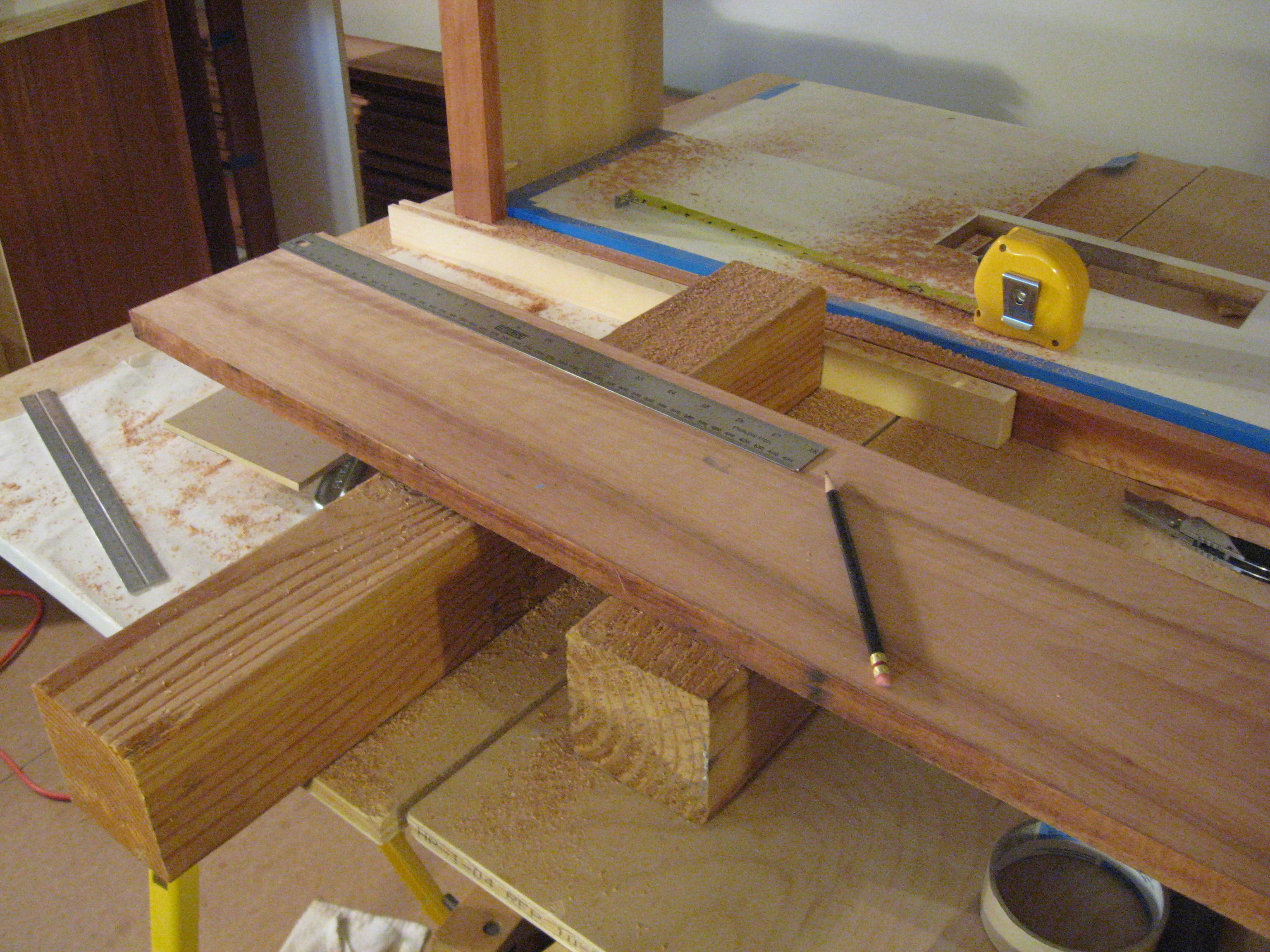
Edge planing the 2" face frame stiles. Four face frames assembled. Now more plywood and melamine must be cut.
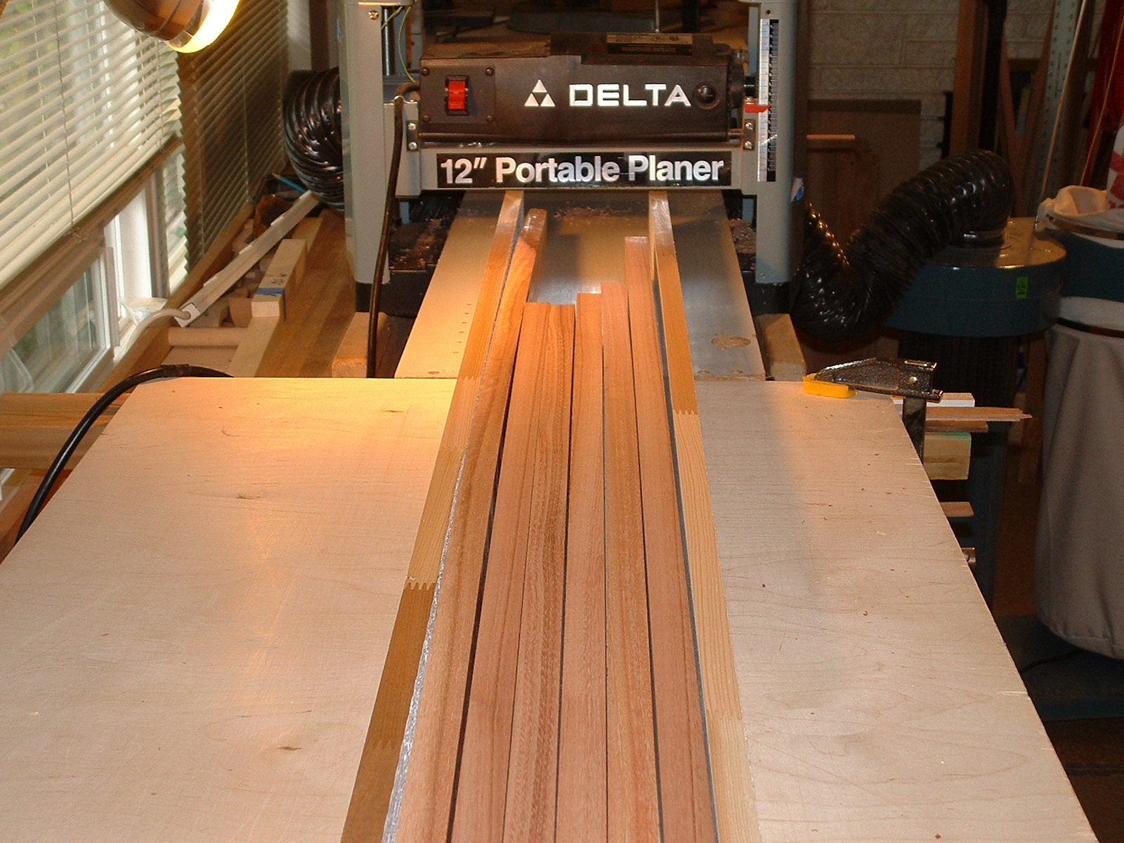
Cabinets two through four shown in some stage of completion.
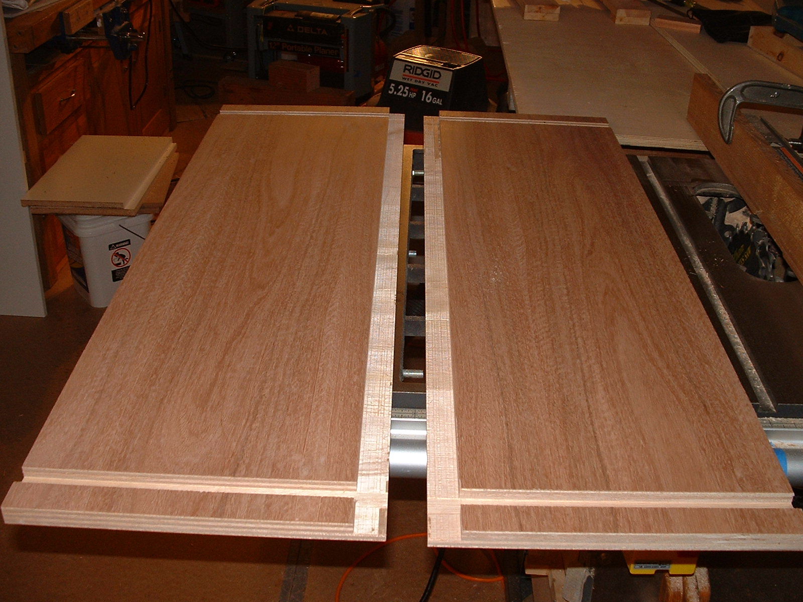
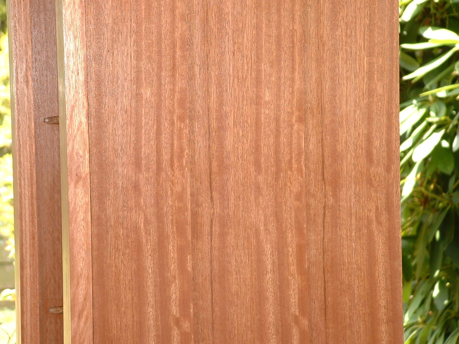
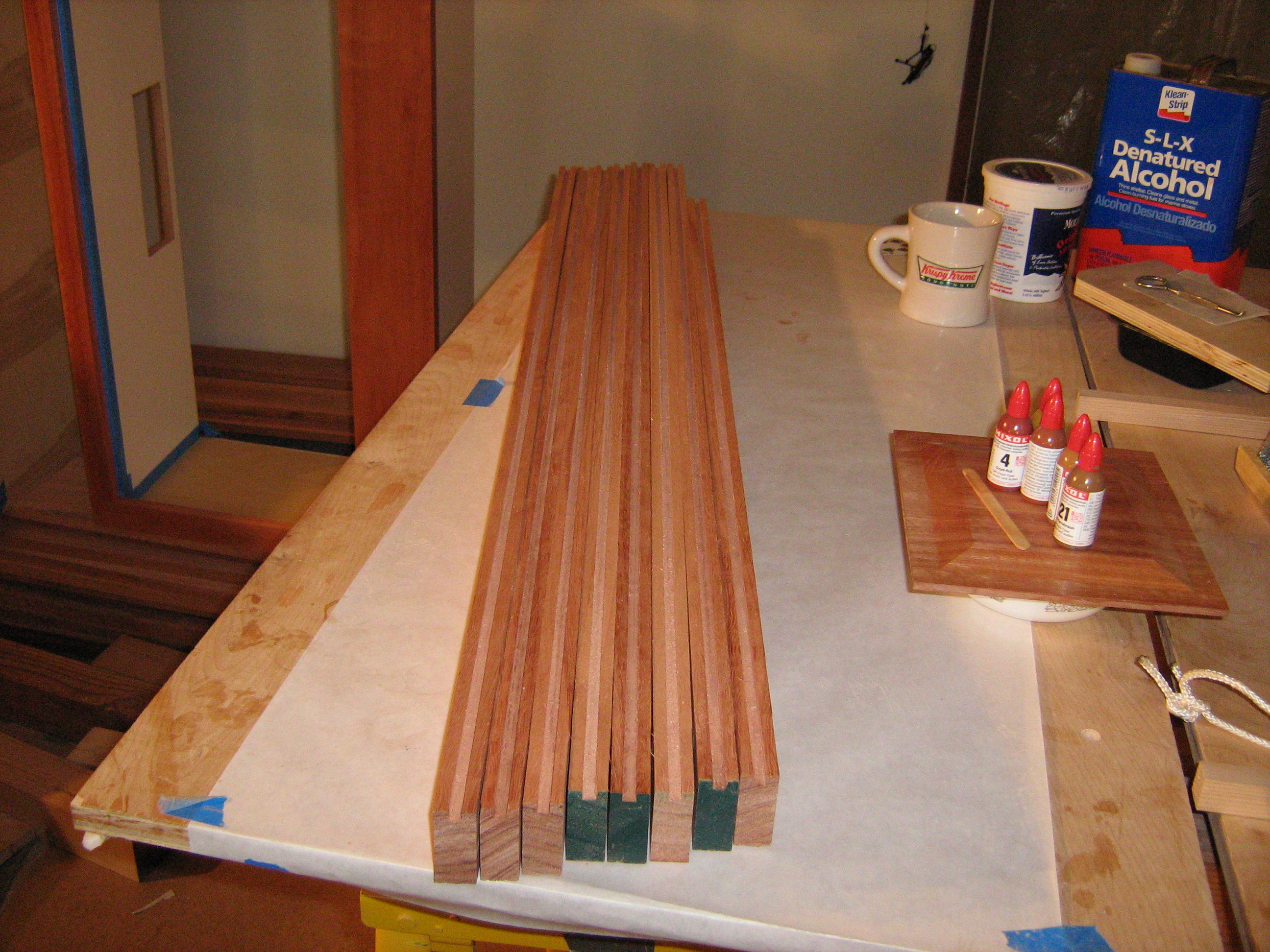
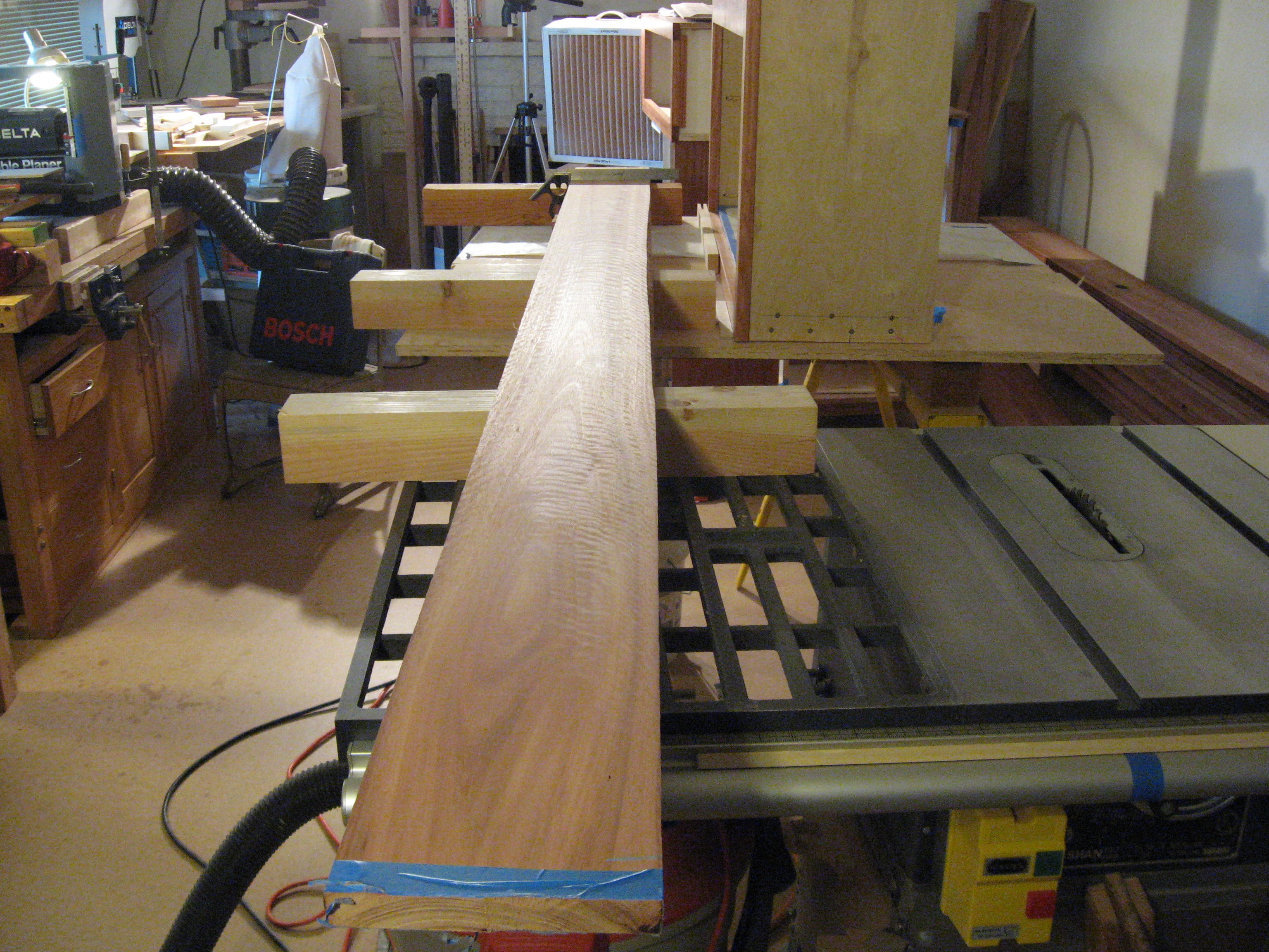
I ripped plain sawn 8/4 x 10" boards. This results in riff sawn and quarter sawn 2" wide clear straight grain boards for the door stiles and rails. These should be very dimensionally stable and resistant to warping. On the left is before and on the right is near the end of planing. I now must sand from 120 up to 600 grit. Fun!
:
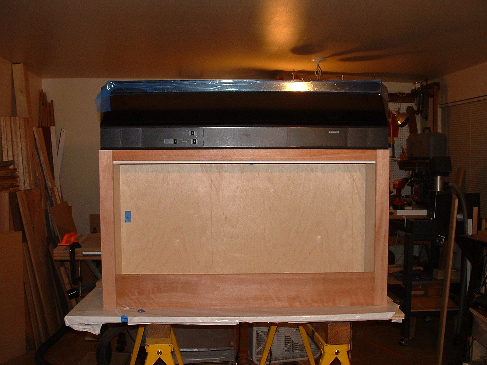
Range hood upside down on cabinet for dry fit.

:
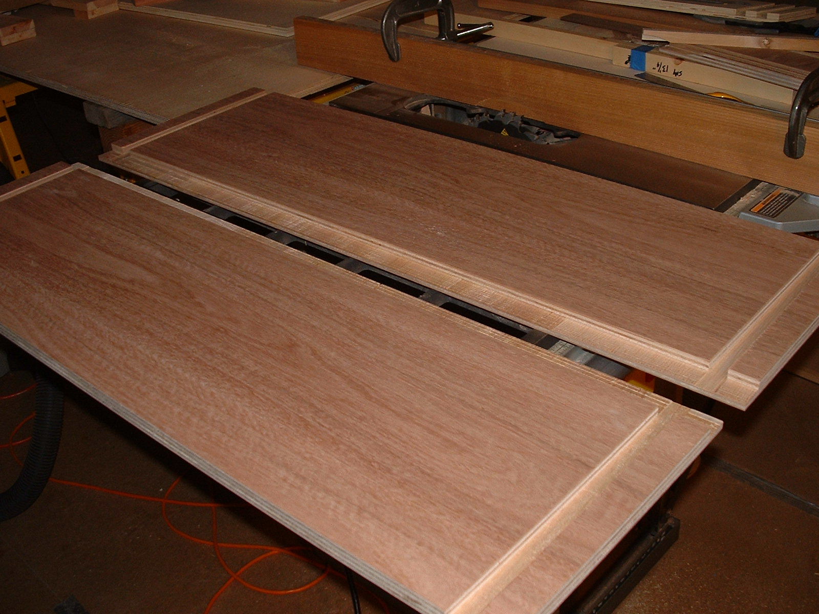
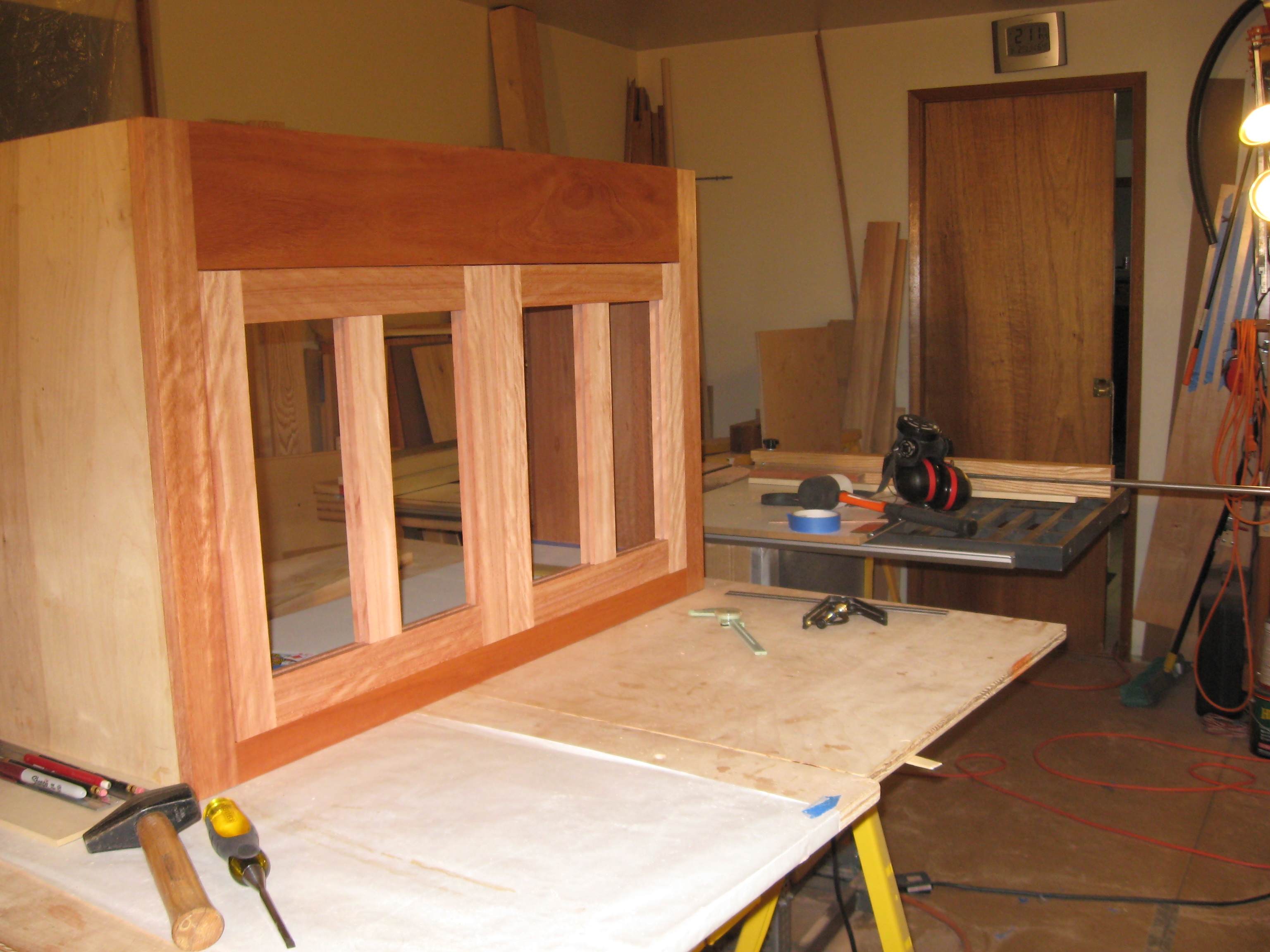
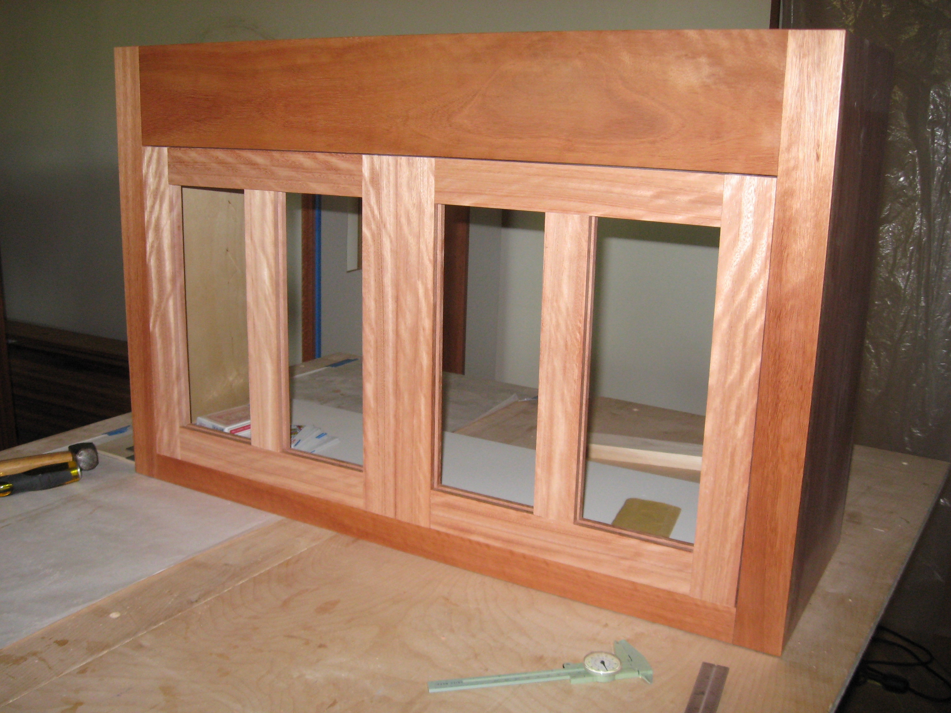
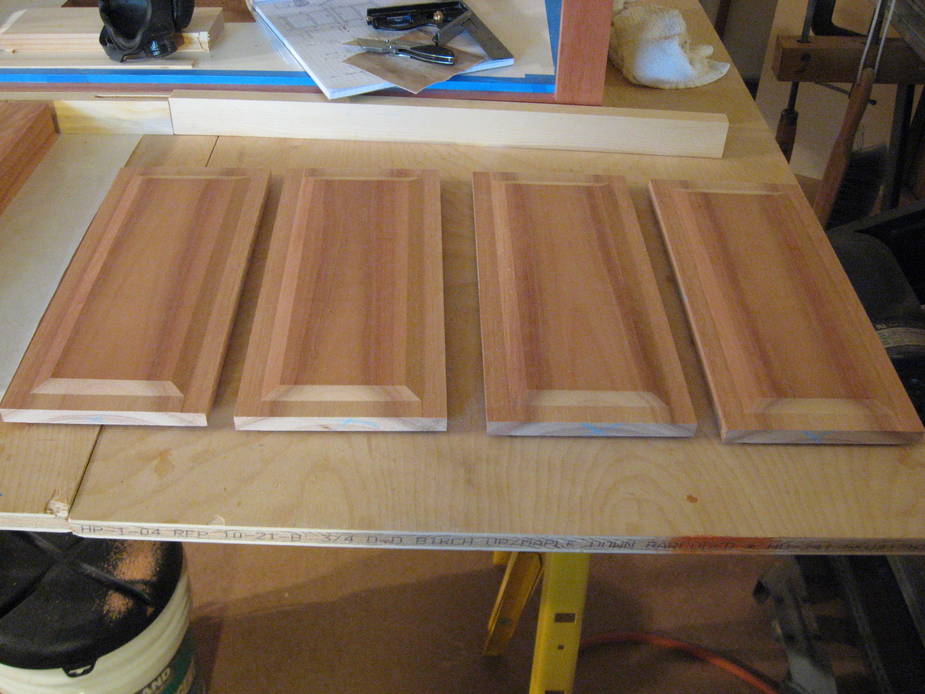
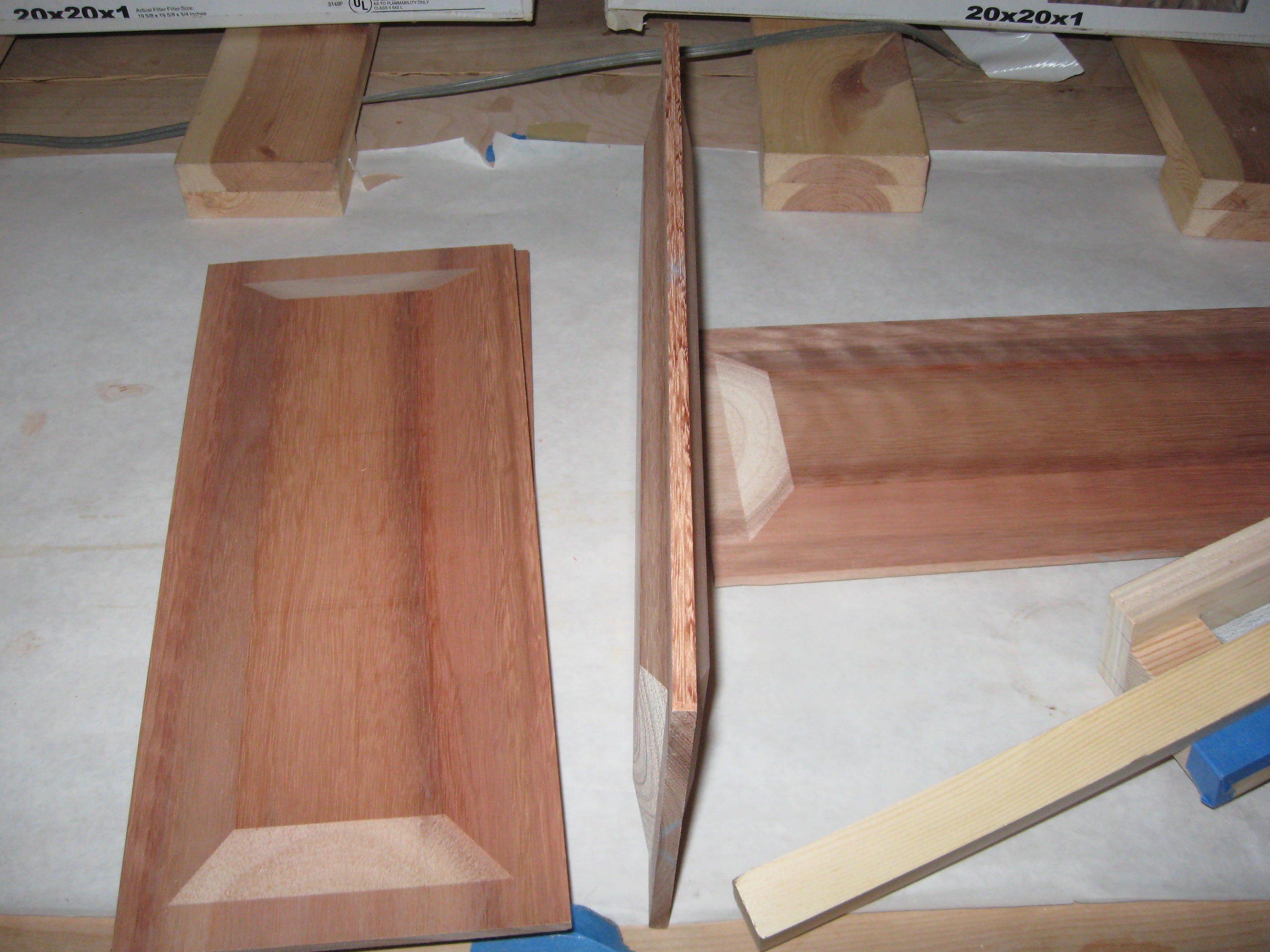
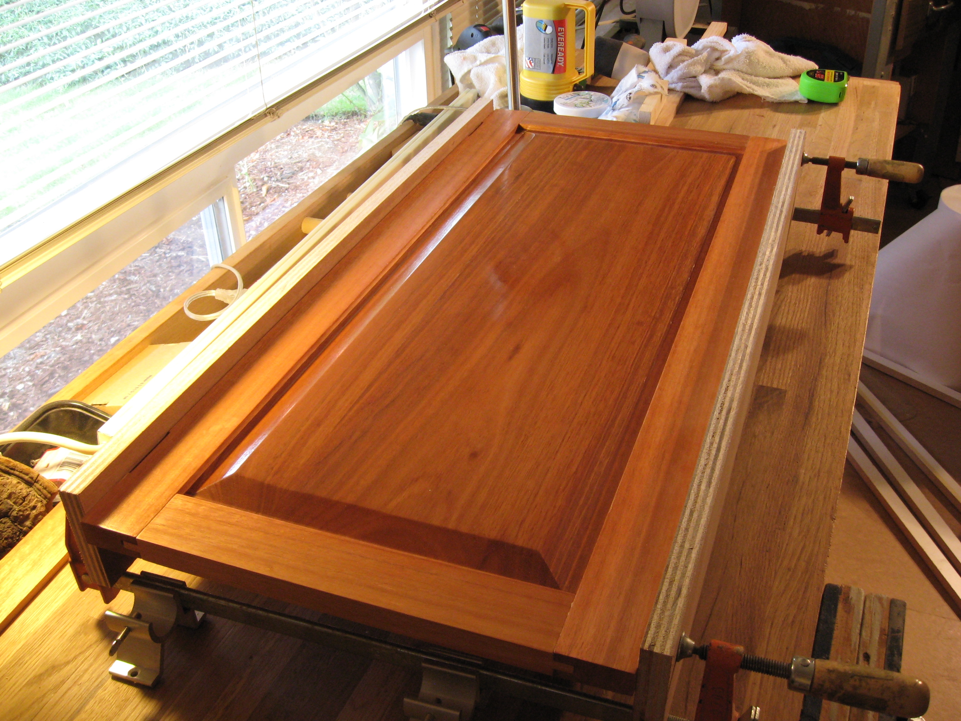
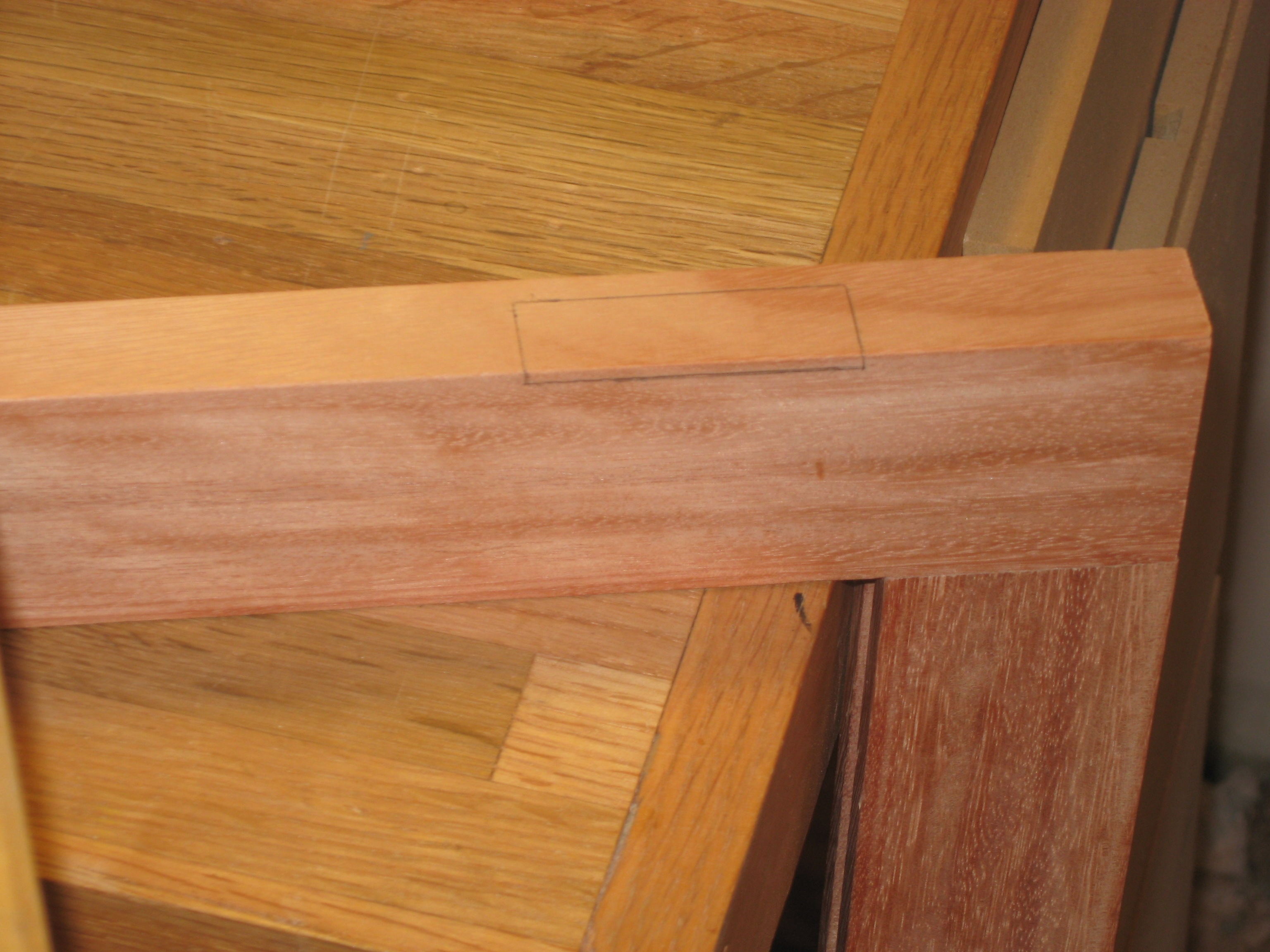
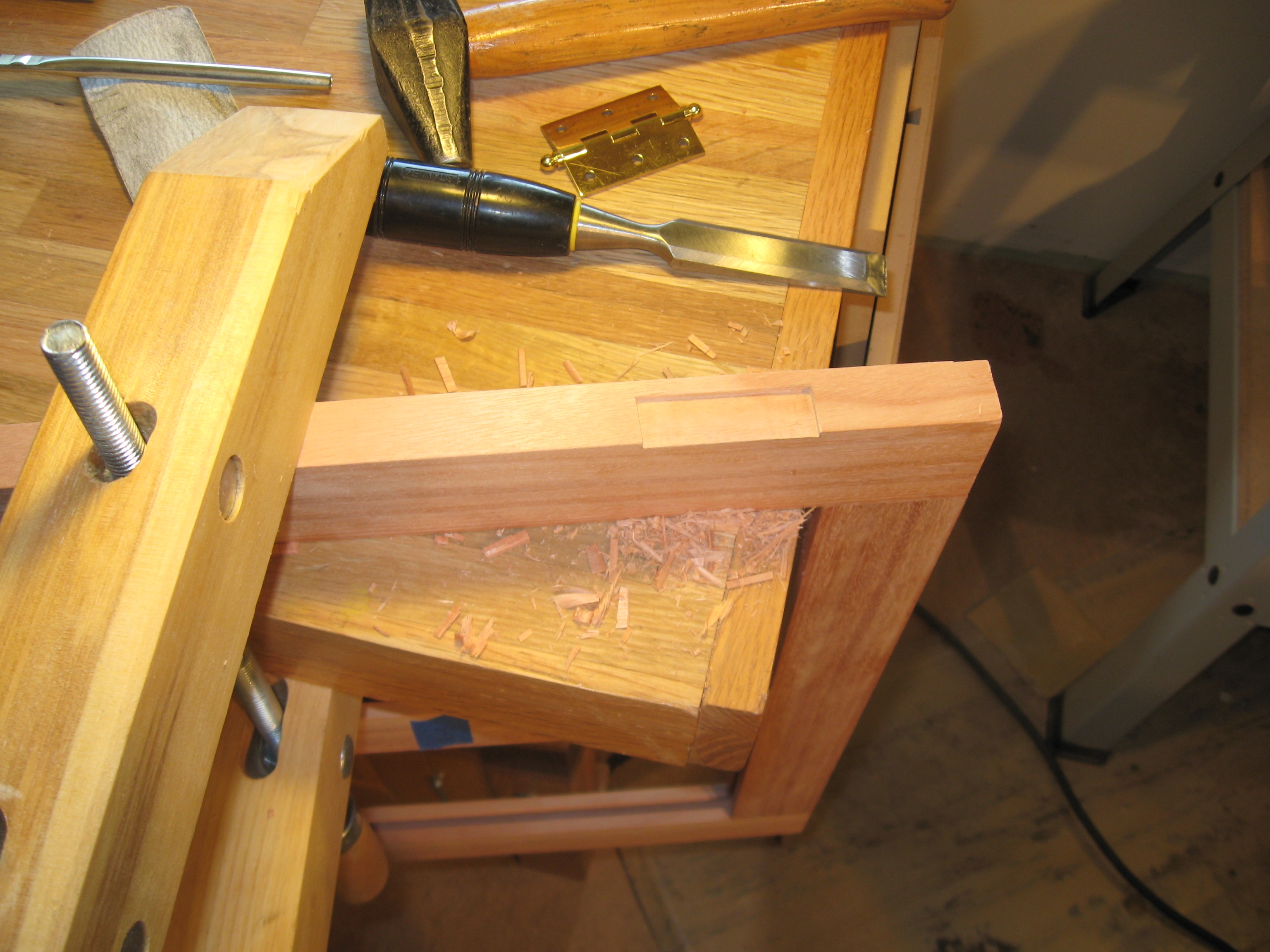
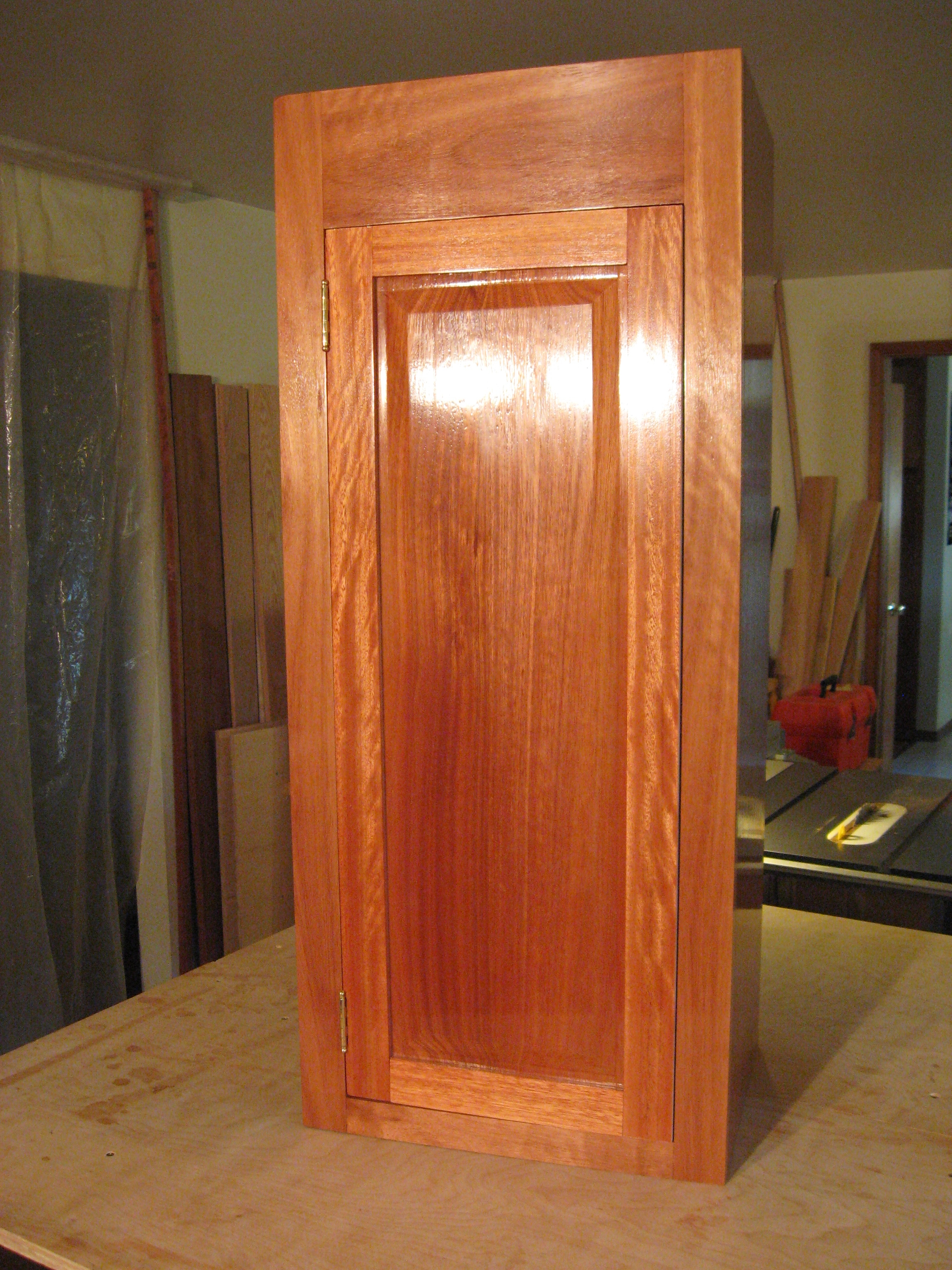
After all the upper cabinets shown in drawing 3 & 4 are assembled I begin the doors. This is the dry fit of the stile and rail frame for the tapered panels. The joint type is a haunched tenon. First few coats of shellac.

The doors are made one at a time
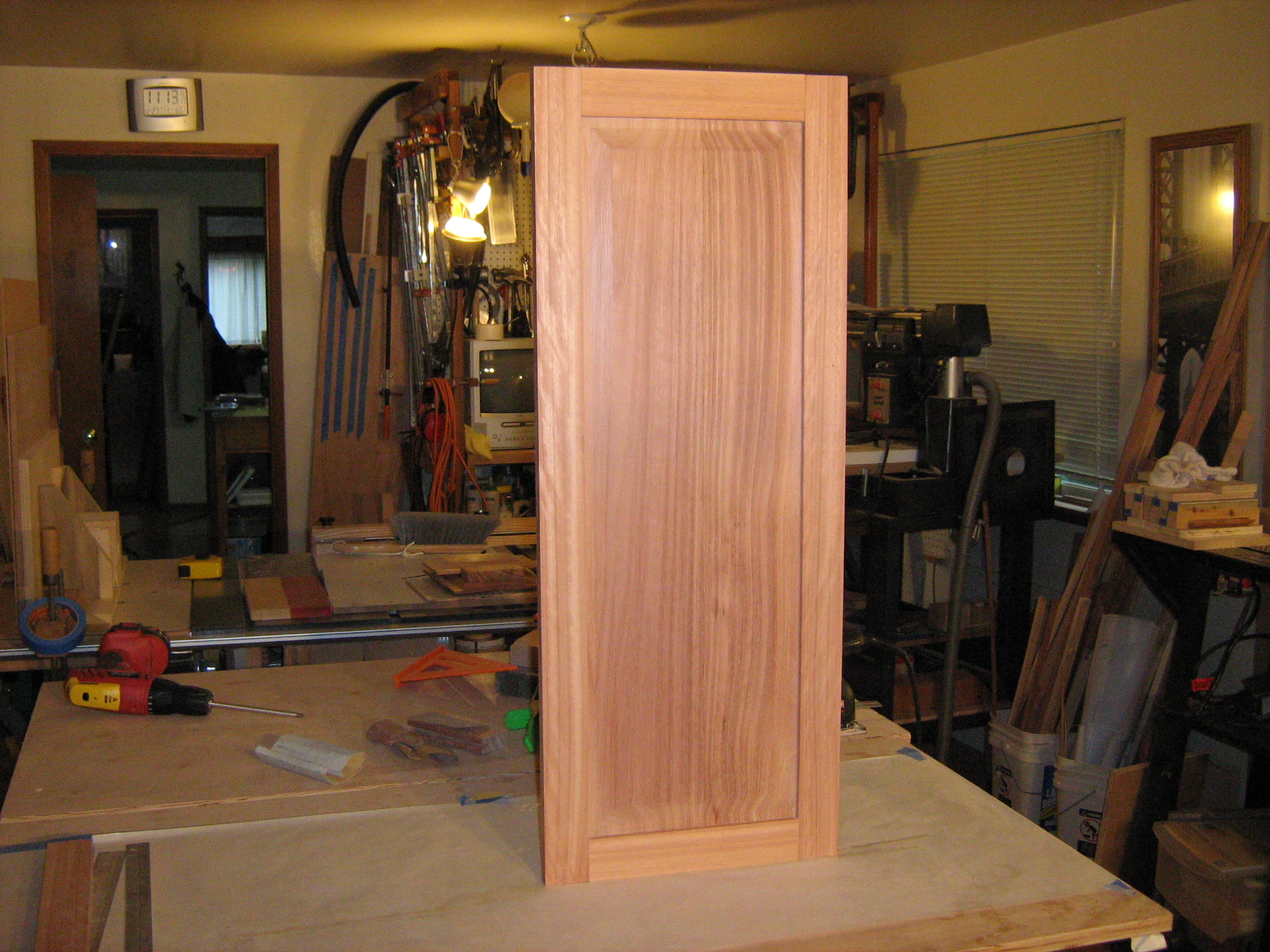
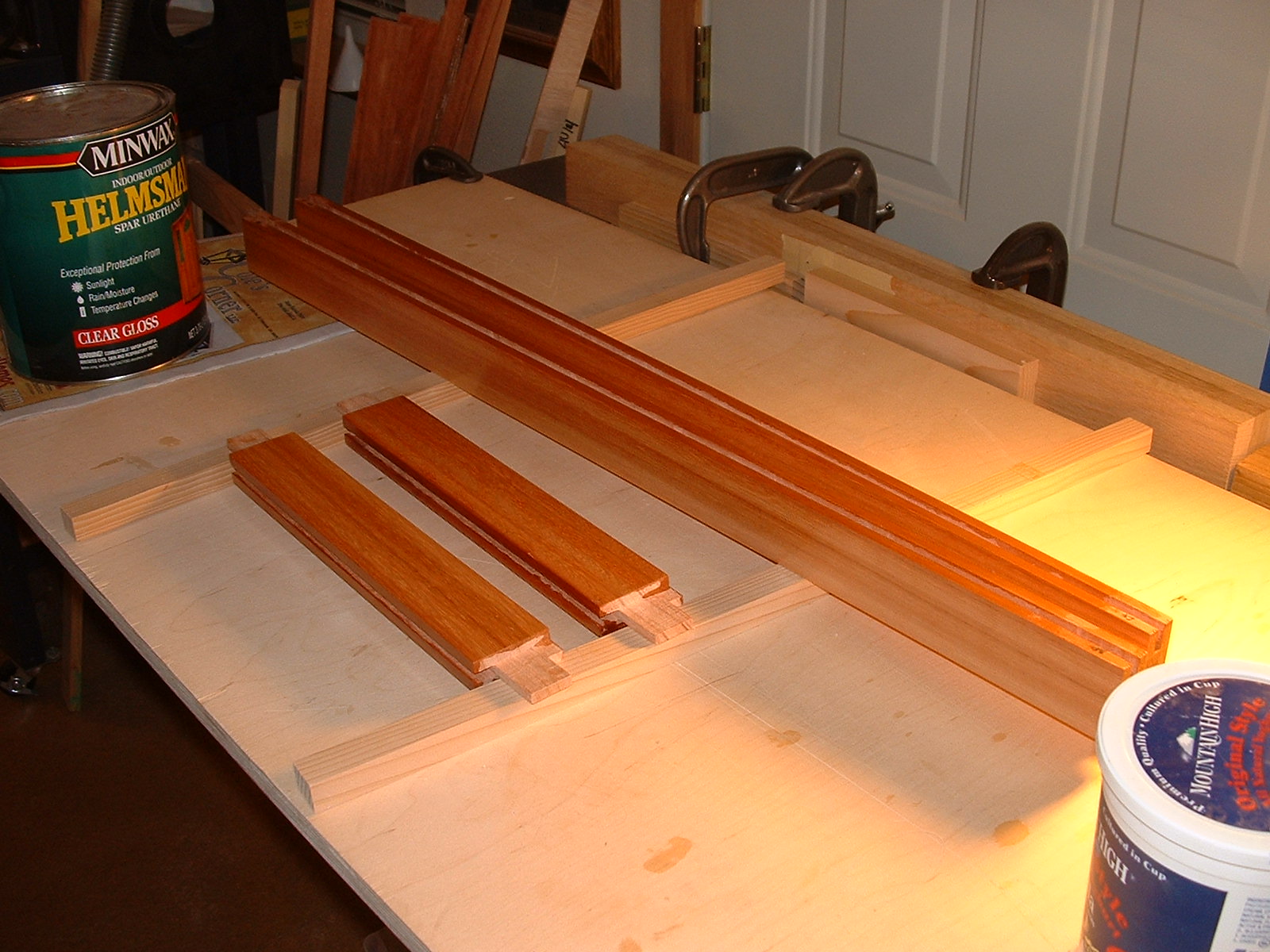
The quartersawn stile and rails are milled in batches.


:
Door Assembly
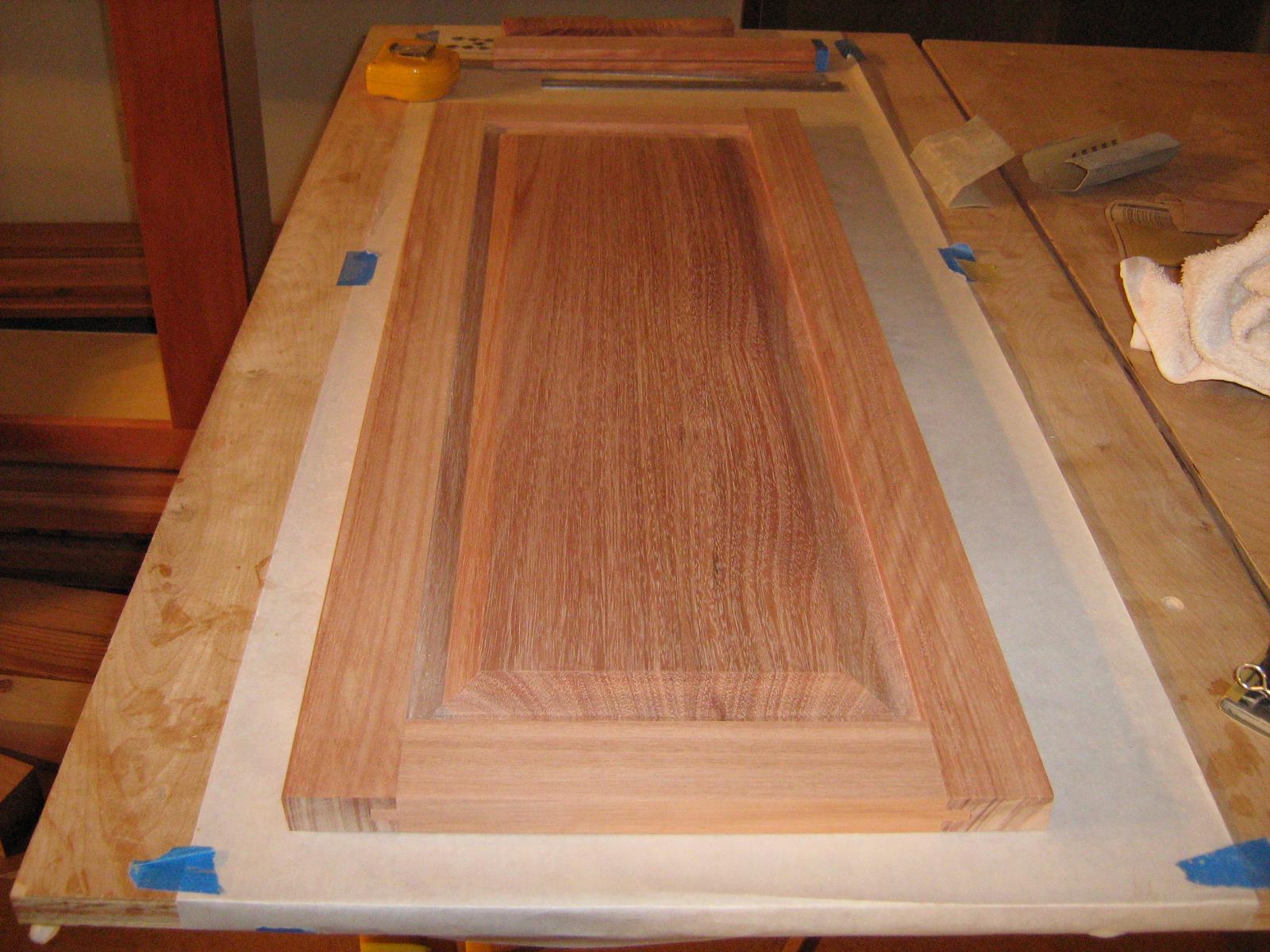
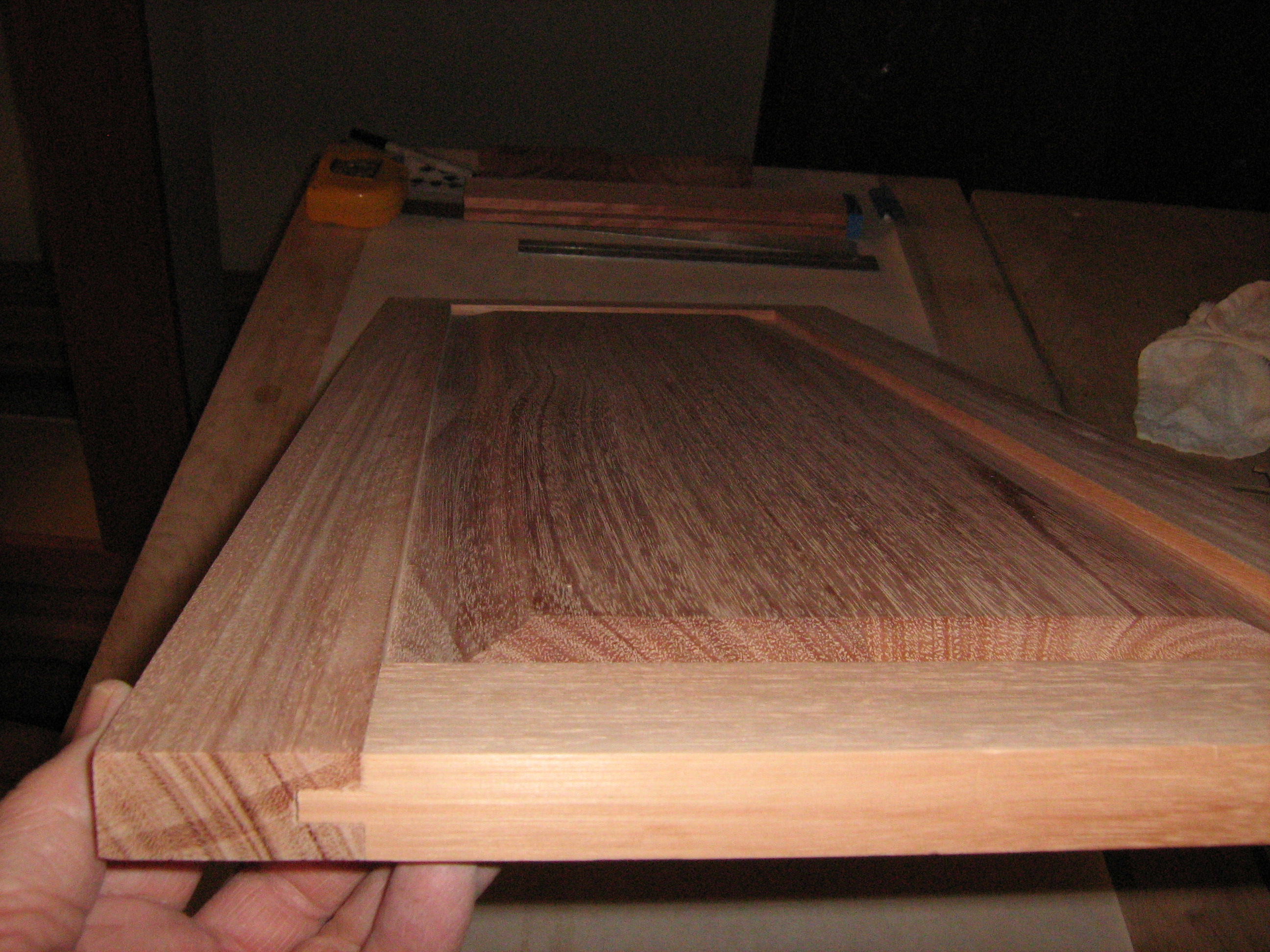
Glue Up of finished panels into un-finished stile and rails. After the glue-up dries I'll mask the panel and apply poly to the stiles and rails. If I apply the poly to all of the door after it is assembled a film will cover the moveable panel and it will no longer float. Therefore after the glue-up dries I'll mask the panel and apply poly to just the stiles and rails.

:
Mortise for Hinge
Mortise hinge into door... now 13 more to go for the wall cabinets. First I mark the mortise, then cut it out, and a final test fit. To test the fit I drag a finger nail over where the wood meets the brass. I am feeling for no snags, a perfectly flush fit. These are real fine top of the line 100% brass Von Morris hinges. They come with 3/4" #6 brass wood screws. To pre-drill for the screws I clamp the hinge in the mortise and drill the holes with a self centering Vix Bit. I always first screw in, by hand, a steel screw of the same exact size as the brass screw will always snap off if I don't do this first. Of course I had to learn this the hard way. So I went to a hobby shop and purchased some small diameter brass tubing. I filed serrations in the end and used it to drill out the busted screw. It works. I whittled a dowel and glued it in place. Now I can cut it flush and re-drill the hole, this time using the steel screw first.

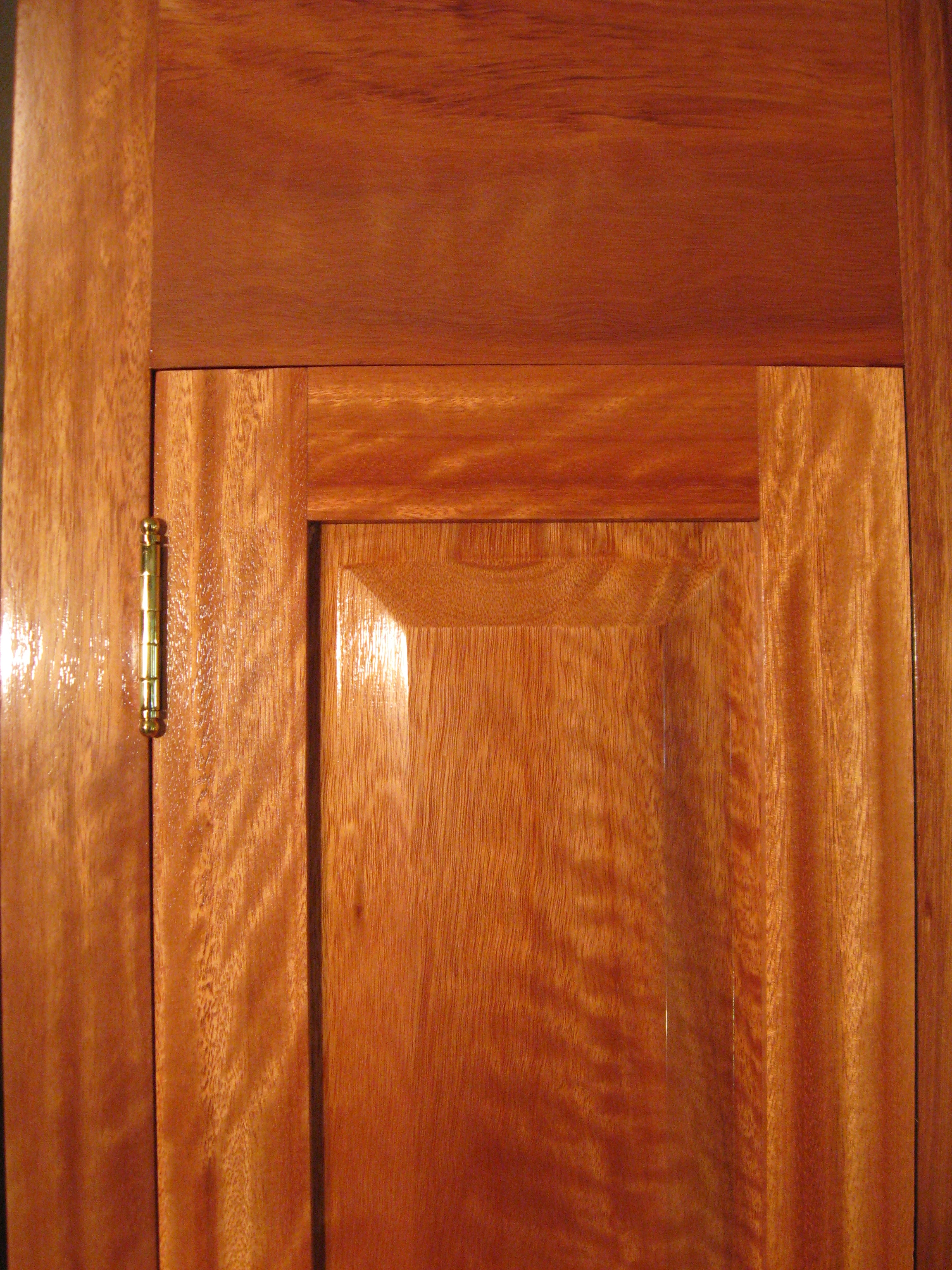
Hinge Markup and Installation
The first two pictures show the transferring of the hinge location from the door to the cabinet. The second two pictures are of the finished hinge installation.
:


:
Every kitchen has to have them.
:
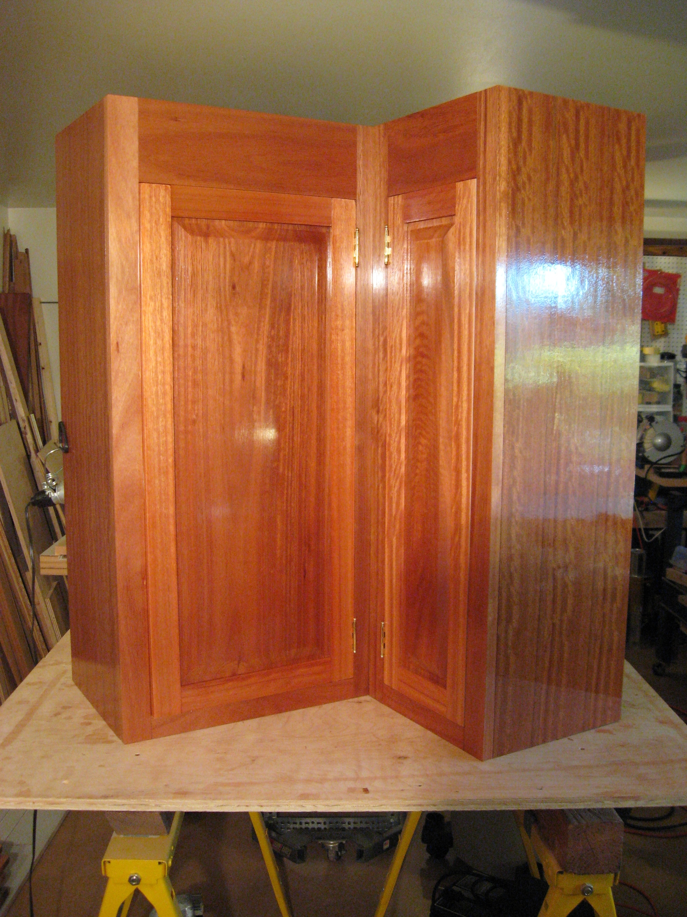
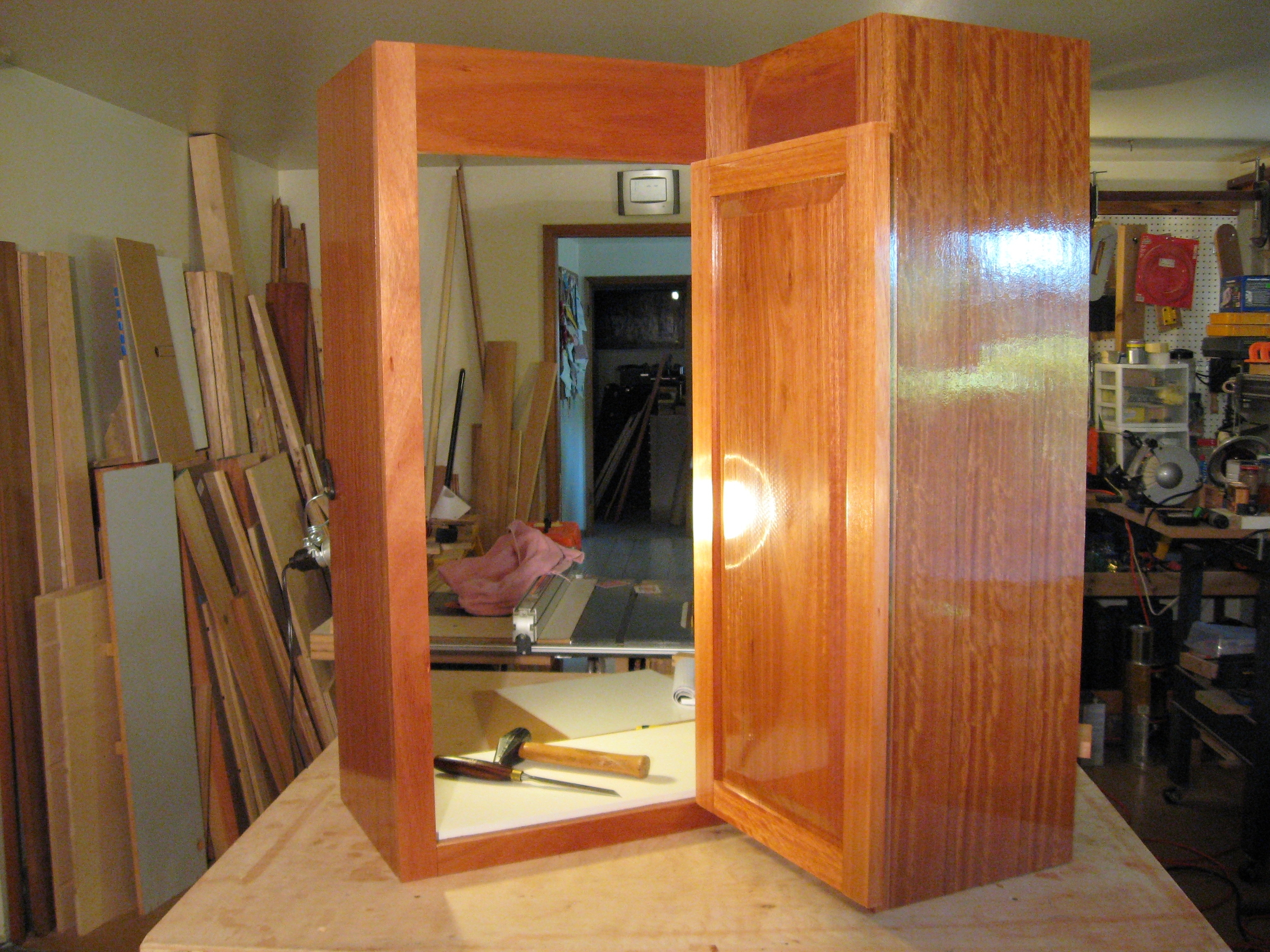
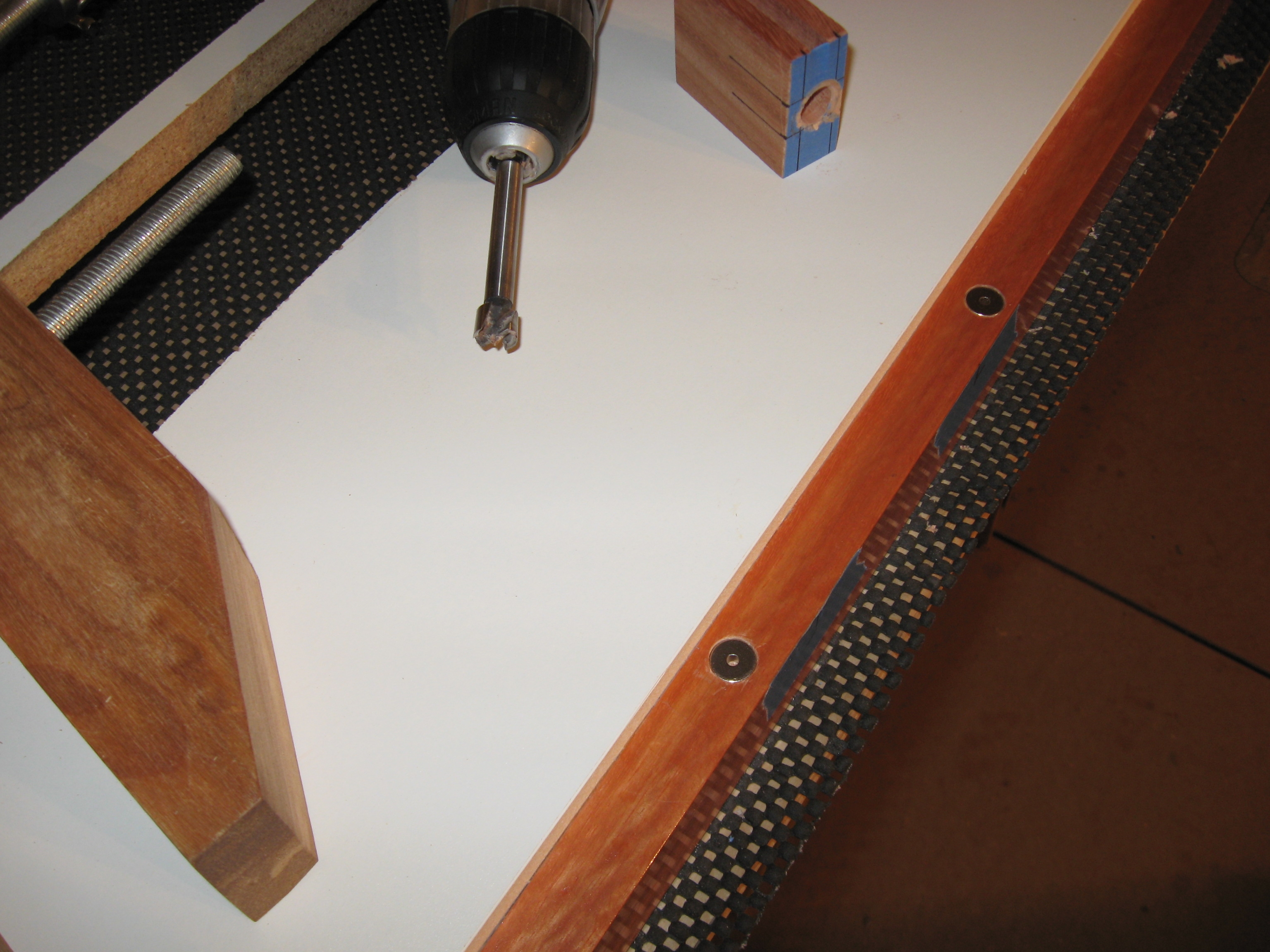
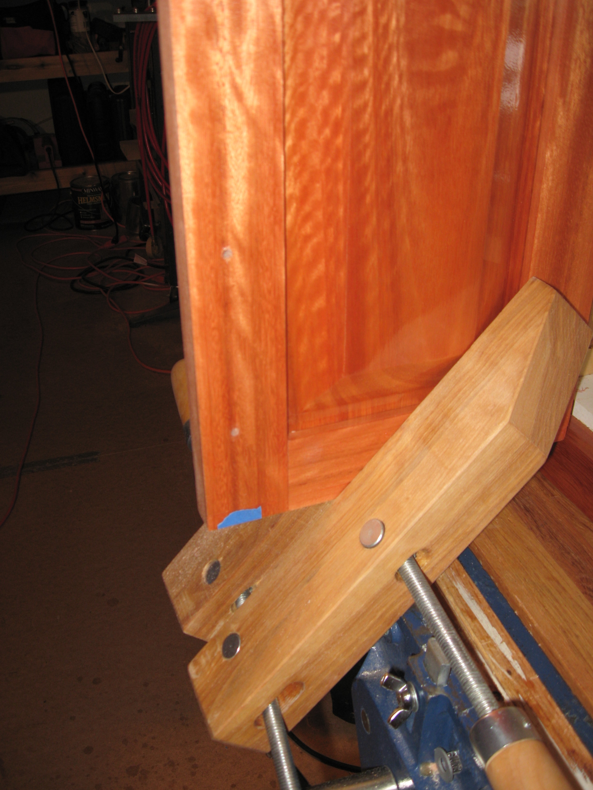
Rare Earth Magnets as Door Latches.
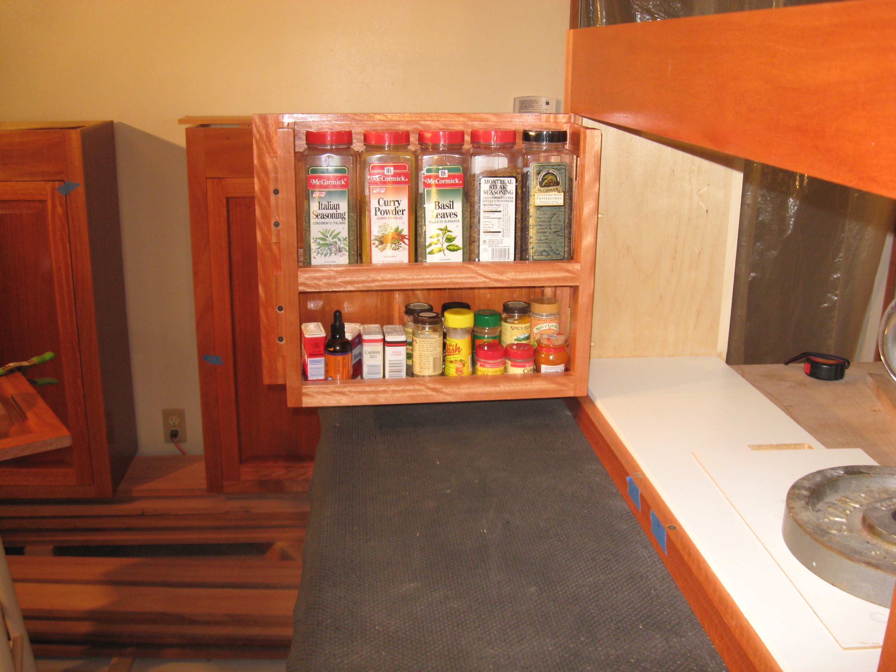
These 12 mm diameter x 4 mm thick N35 axially magnetized ring shaped Neodymium rare earth magnets make real fine door catches. I was looking for a latch that did not disrupt the cabinet floor surface and worked with inset doors. They are set just below the surface in the face frame and the door rails. I drill out the hole with a forstner bit and use 6 minute epoxy to secure the magnet in the hole. The wood block is the jig that sets the register and depth. N35 is the specification of a weak rare earth magnet where N52 is a very strong magnet. The rare earth magnets are, by default, much stronger that iron magnets. The magnets used here must be within less than an inch of each other to close the door. With this small a magnet, it doesn't take much force to open the door. But if the door is slung closed, the door it stays closed and doesn't bounce back open. Perfect for any of these heavy doors, even the ones with a full spice rack attached on the inside.
:
DOOR HANDLES
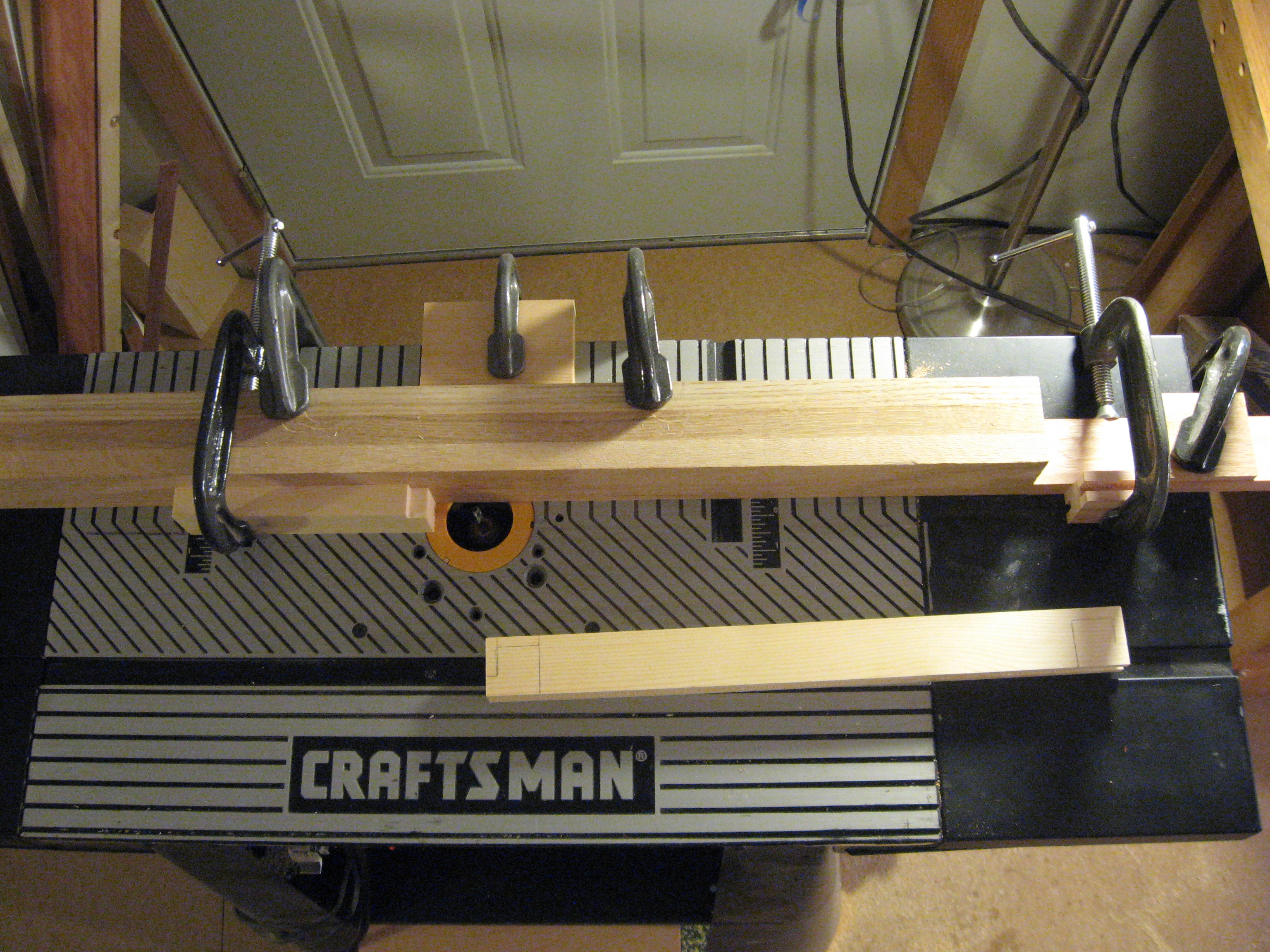
I first fabricated a jig that the registers of the handle to the door frame, sets the exact distance between the holes (96 mm) and establishes the perpendicular angle for the holes. The first and second pictures show the jig clamped into position. Tape is used under the jig in the front to prevent marring and a backing board on the back to prevent chip out when the bit exits the wood. Lyptus will almost always chip out, a very brittle wood. The #2 Jorgensen clamp is only used to hold the door in position when drilling. The third and forth pictures show two good clean holes with no marring or chip out. The fifth picture shows the brass handle installed.


: